
Rear mountable cutter device for a hunting arrow

a cutter device and rear mount technology, applied in the field of hunting arrows, can solve the problems of inability to locate animals, difficulty in tracking wounded animals, and limited use of cutter blades in broad heads, etc., and achieve the effect of accurate mounting of cutter members and/or vanes

Inactive Publication Date: 2011-12-20
SHAWSHEEN RIVER ARCHERY PRODS
View PDF29 Cites 13 Cited by
  • Summary
  • Abstract
  • Description
  • Claims
  • Application Information

AI Technical Summary

Benefits of technology

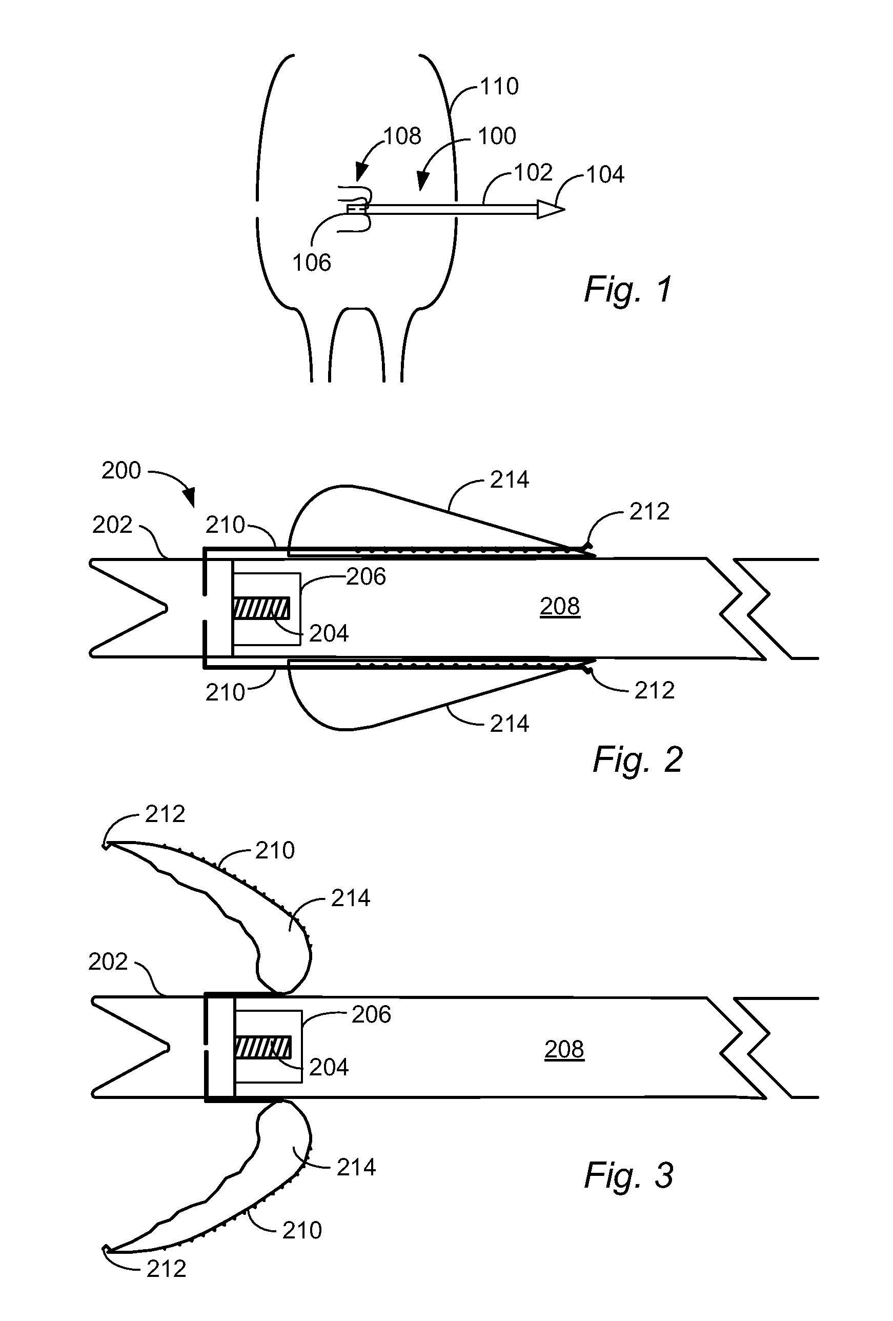
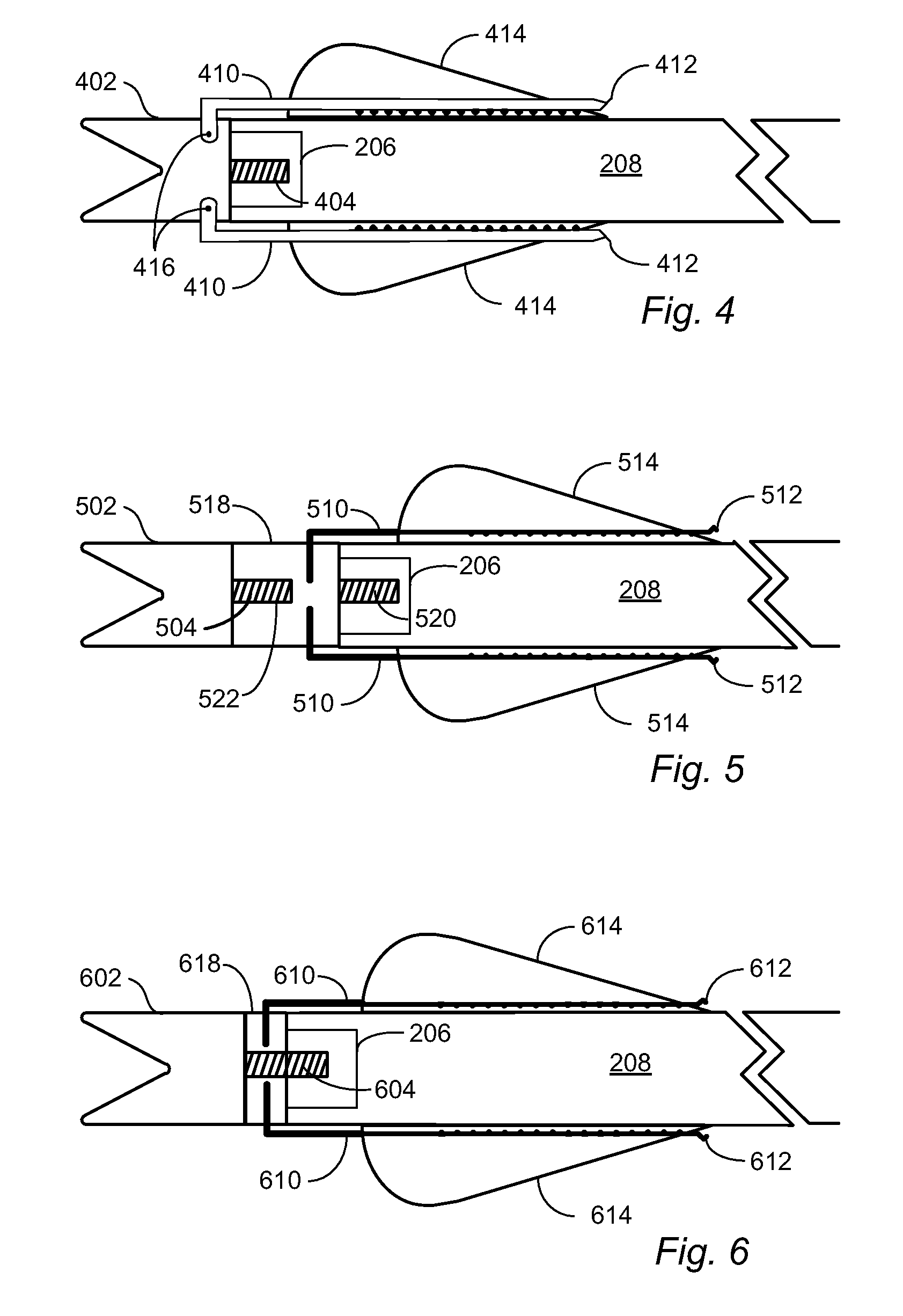
"The patent describes a device that can be attached to the back of a hunting arrow to cut through the target animal. It includes a mounting component that is attached to the back of the arrow and cutting members that can be wires, blades, or a part of a stamped metal. When the cutting members impact the target animal, they deform or rotate outward from the arrow shaft to create a larger entry wound and more internal wounds than would be possible without the device. An alignment tool is also included to help accurately mount the cutting members and vanes on the arrow. Overall, this device improves the effectiveness and accuracy of hunting arrows."

Problems solved by technology

If the entry and exit wounds close quickly, tracking of the wounded animal may become more difficult and the animal may not be able to be located.
The size of the cutter blades used in a broad head, however, is limited in practice by the size of the broad head.
Additionally, if deployed cutter blades at the forward end of an arrow are too large, the broad head will not be as likely to pass through the target animal and create an exit wound.

Method used


Image

  • Rear mountable cutter device for a hunting arrow
  • Rear mountable cutter device for a hunting arrow
  • Rear mountable cutter device for a hunting arrow

Examples


Embodiment Construction

[0028]U.S. Provisional Application No. 61 / 194,980 filed Oct. 2, 2008 and titled Rear Mountable Assembly for a Hunting Arrow is incorporated herein by reference in its entirety.

[0029]In accordance with the present invention, a rear mountable cutter device for a hunting arrow is described. The rear mountable cutter device includes at least one mounting component configured for mounting a plurality of elongated cutting members at the rearward end of an arrow shaft. The plurality of elongated cutting members have a back end and a forward end. The back end of each of the plurality of elongated members is mechanically coupled to a mounting component. The mechanical coupling may constitute an attachment that fixedly mounts the cutting members to the component, an attachment that permits pivotal rotation of the cutting members with respect to the mounting component. The mechanical coupling may also encompass fabrication of the cutting members as a single piece with a mounting component. Upo...


PUM


Abstract

A rear mountable cutter device for a hunting arrow is mountable to an arrow shaft. The device includes a plurality of elongated cutting members that are positioned along the rear end of the arrow shaft following mounting of the cutter device to the shaft. The cutting members are configured such that when the forward end of the cutting members engage a target animal, the cutting members deflect outward of the shaft to produce an enlarged wound in the target animal.

Description

CROSS REFERENCE TO RELATED APPLICATIONS[0001]The present application claims priority benefit of U.S. Provisional Patent Application No. 61 / 194,980 filed Oct. 2, 2008.STATEMENT REGARDING FEDERALLY SPONSORED RESEARCH OR DEVELOPMENT[0002]Not ApplicableBACKGROUND OF THE INVENTION[0003]The present invention pertains to hunting arrows and more specifically, to a rear mountable cutter device or vane assembly that is mountable to the rear end of an arrow shaft.[0004]When hunting with a bow and arrow, it is generally understood that it is desirable to create an entry and an exit wound in a target animal. By creating an entry and exit wound, it is likely that bleeding from the wounds will permit the hunter to track and locate the target animal due to bleeding from the respective wounds. If the entry and exit wounds close quickly, tracking of the wounded animal may become more difficult and the animal may not be able to be located.[0005]To address this problem, hunting arrows have been provide...

Claims


Application Information

Patent Timeline
Patent Type & Authority Patents(United States)
IPC IPC(8): F42B6/04
CPCF42B6/04F42B6/06
Inventor MACKEY, JR., JAMES F.CAMARA, JOSEPH M.
Owner SHAWSHEEN RIVER ARCHERY PRODS
Learn More