Cooling system and method for an electric motor

a technology of cooling system and electric motor, which is applied in the direction of magnetic circuit rotating parts, lighting and heating apparatus, magnetic circuit shape/form/construction, etc., can solve problems such as motor overheating, and achieve the effect of bringing the motor to the desired operating temperature more quickly

Active Publication Date: 2011-12-20
FORD GLOBAL TECH LLC
View PDF36 Cites 46 Cited by
  • Summary
  • Abstract
  • Description
  • Claims
  • Application Information

AI Technical Summary

Benefits of technology

[0010]In another embodiment, the end cap of the electric motor contains hydraulic and thermal management components, including, for example, electronic valves, electronics control unit, a pump for the low-temperature coolant, electronic sensors, and a hydraulic accumulator. These components are used to modify cooling of the motor. For example, it may be desirable to partially close a valve in the high-temperature coolant passage to allow faster motor warm-up. By allowing faster warm-up, parasitic drag caused by the motor lubricant may be reduced.
[0015]An advantage of the present disclosure is that having the heat exchanger and hydraulic components for cooling the motor placed in the end cap, the cooling level required for the motor's application can be met by selecting an end cap assembly with the desired cooling capacity, while little or no change is made to the motor itself. In this way, a single motor design can be used in many vehicle applications with various end caps that can be coupled to the motor to satisfy the cooling requirements of the particular vehicle configuration.

Problems solved by technology

It is known that the motor can overheat depending on the severity of the operating condition to which it is subjected.

Method used


Image

  • Cooling system and method for an electric motor
  • Cooling system and method for an electric motor
  • Cooling system and method for an electric motor

Examples


Embodiment Construction

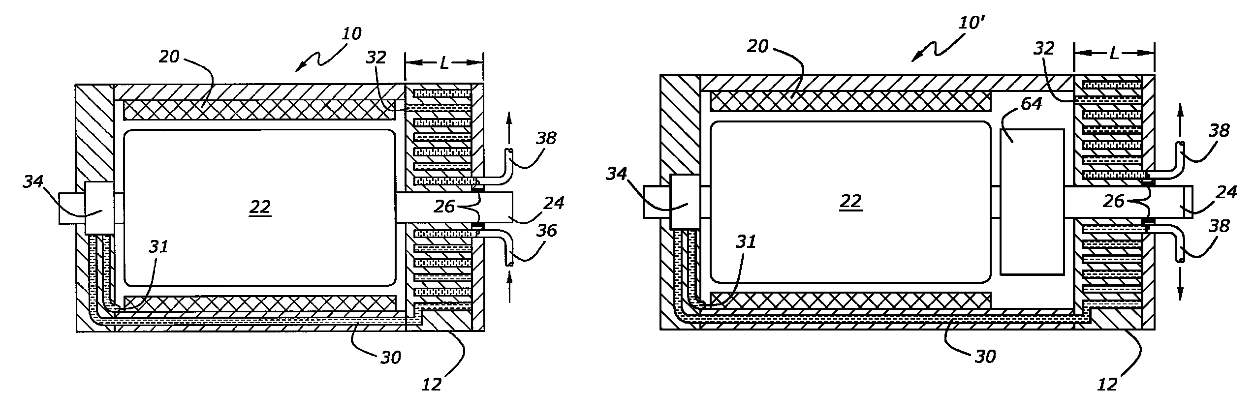
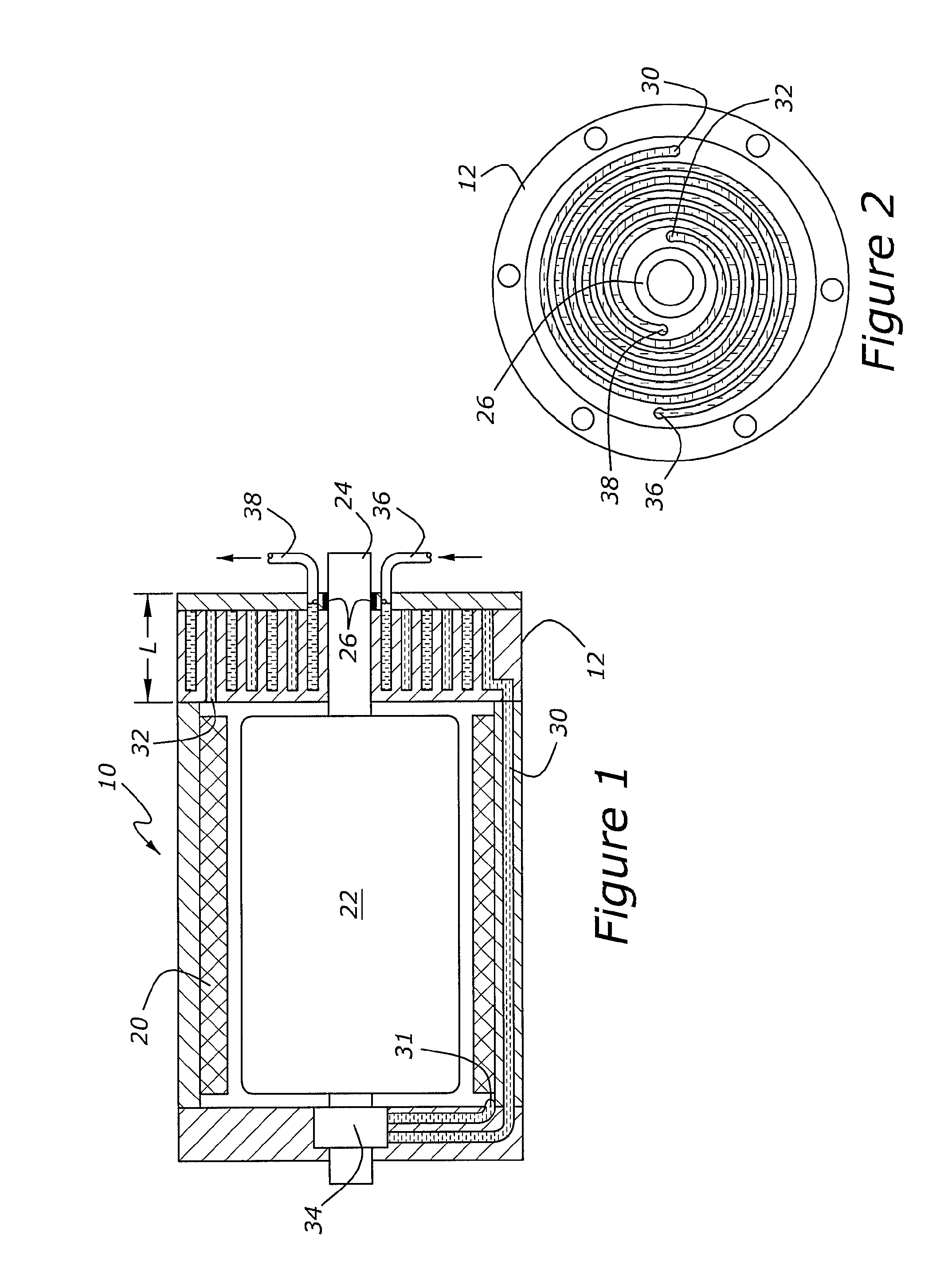
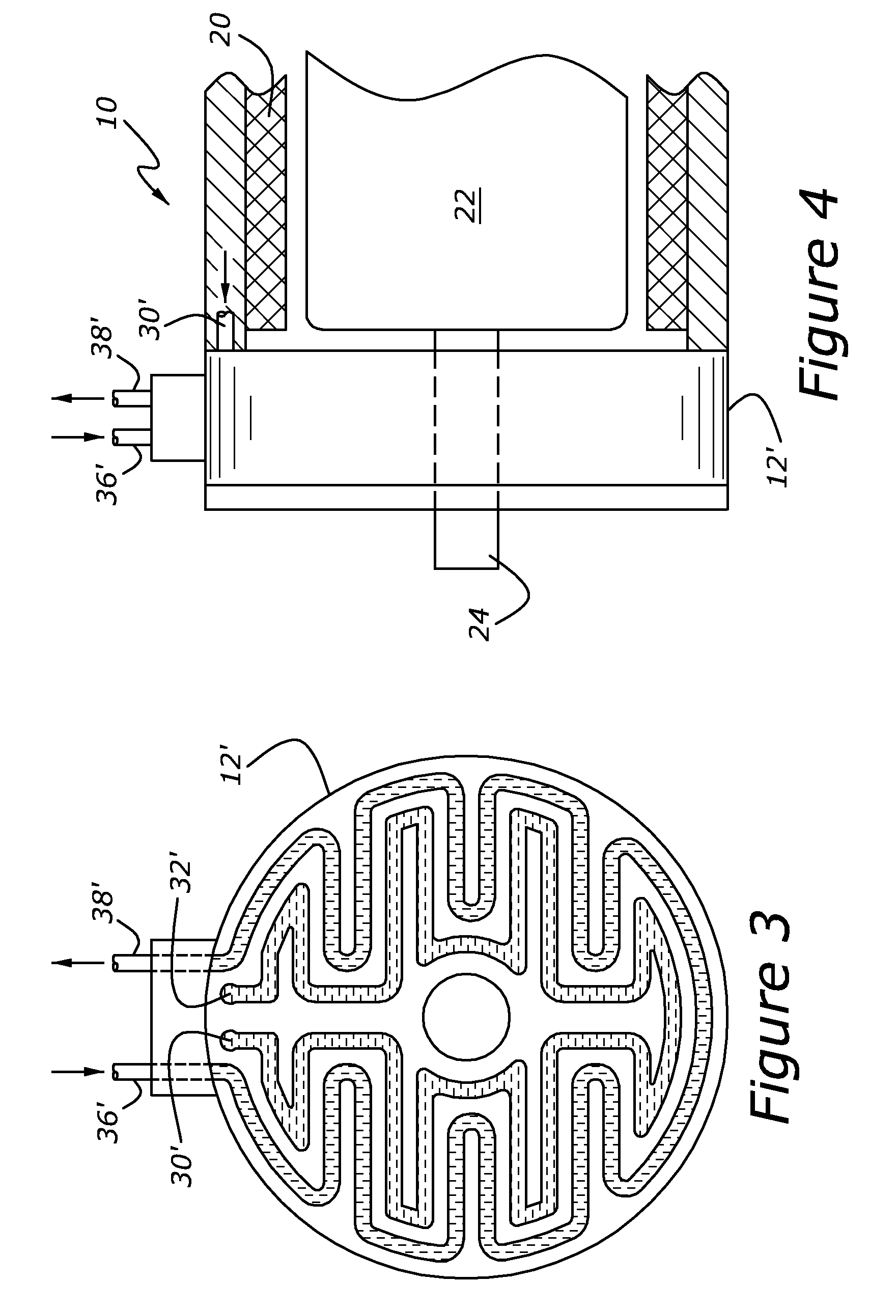
[0031]A motor 10 is shown in FIG. 1 which has an end cap 12. Motor 10 has a stator 20 with a rotor 22 inserted into stator 20. Output shaft 24 is connected to rotor 22. An end of output shaft 24 goes through end cap 12. Output shaft 24 can extend out at one end of motor 10 only or at both ends depending on the desired configuration. The end cap has a seal and bearing 26, which can be integrated or separate components. Motor 10 has a liquid coolant circulating within, contacting both the stator and rotor, or the stator only. In one embodiment, the liquid is oil. Thermal energy is extracted from motor 10 via coolant circulation. Coolant enters the end cap 12 at 30 and exits at 32, being pumped by pump 34 which is driven by shaft 24. Pump 34 has a coolant pickup 31 at the bottom of motor 10. Within end cap 12 is a liquid-to-liquid heat exchanger being supplied a second liquid coolant at 36 and removed at 38. The second liquid can be a water-based coolant, in one embodiment. In another ...


PUM


Abstract

An electric motor which has a separate end cap heat exchanger, through which a liquid coolant is passed, is disclosed. In one example embodiment, the electric motor is a traction motor or motor-generator in a hybrid electric vehicle having an internal combustion engine. Additionally, in one embodiment, the heat exchanger has a low-temperature coolant loop configured to extract energy from the motor coolant. The electric motor may be installed in a variety of vehicles or other applications having greatly differing cooling requirements. By placing the heat exchanger and control componentry in the end cap, the cooling capability of the electric motor can be changed by selecting an end cap with the appropriate heat transfer characteristics and control componentry to provide the desired cooling. Consequently, a single electric motor, with a variety of end cap choices, can be used in a variety of applications.

Description

BACKGROUND[0001]1. Technical Field[0002]The development relates to providing cooling for electric motors.[0003]2. Background Art[0004]Electric motors can be used as a power source in vehicles. It is known that the motor can overheat depending on the severity of the operating condition to which it is subjected.[0005]Most automotive vehicle manufacturers offer a variety of electric and hybrid electric vehicles for sale. The offerings differ in their weight, hauling capacity, and duty cycle. For vehicles that include an electric traction motor or a motor generator, or other high-power motor, the maximum power demands on the motor differ greatly depending on the application. The maximum power affects the cooling needs of the motor. Cooling, by circulating a liquid within an electric motor, is known in the prior art. However, cooling systems are designed for a particular motor used in a particular vehicle configuration with a particular cooling demand. For an alternate vehicle configurat...

Claims


Application Information

Patent Timeline
Patent Type & Authority Patents(United States)
IPC IPC(8): H02K1/32H02K9/00H02K5/20H02K5/18H02K3/24
CPCB60K6/48H02K9/19B60K2001/003F28F2210/10H02K5/20H02K9/22Y02T10/6221Y02T10/641Y02T10/62Y02T10/64H02K9/227H02K5/203H02K9/197
Inventor PERKINS, WILLIAM PAUL
Owner FORD GLOBAL TECH LLC
Why Eureka
Try Eureka