Backlight apparatus and liquid crystal display apparatus

a technology of liquid crystal display and backlight, which is applied in the direction of illuminated signs, display means, instruments, etc., can solve the problems of led brightness aging degradation, shortening the life of led lights, and aging degradation, and achieve the effect of reducing the brightness of non-uniform lights

Active Publication Date: 2011-12-20
PANASONIC CORP
View PDF7 Cites 10 Cited by
  • Summary
  • Abstract
  • Description
  • Claims
  • Application Information

AI Technical Summary

Benefits of technology

[0010]An object is to provide a backlight apparatus and a liquid crystal display apparatus that enable a balance of brightness to be maintained over the entire area of a display screen, and long life to be achieved. A further object is to provide a backlight apparatus and liquid crystal display apparatus that enable nonuniformity of brightness to be reduced in an outputting surface.
[0017]A backlight apparatus that is used in a liquid crystal display apparatus having a liquid crystal panel as a display screen, achieves the above objects by comprising a substrate having an opposed section placed opposite the rear surface side of the liquid crystal panel, a plurality of light emitting diodes placed with nonuniform placement density on the opposed section, a diffuser plate upon which light emitted from the plurality of light emitting diodes is input and that has a diffusing action on the input light and outputs diffused light toward the liquid crystal panel side, and a current supplying section that supplies to the plurality of light emitting diodes a current that causes the plurality of light emitting diodes to emit light that illuminates the liquid crystal panel; and by having the current supplying section supply a lower current to a light emitting diode placed in an area having a higher ambient temperature within the area of the opposed section, wherein light emitting diodes to which a lower current is supplied are placed with higher density adjacent to another light emitting diode, and the distance between the opposed section and the diffuser plate is greater the lower the placement density of a position.

Problems solved by technology

However, a property of an LED is that the higher its ambient temperature, the faster is the aging degradation of its brightness and the shorter is its life.
Also, increasing the brightness of an LED by increasing its drive current amount or the like is a cause of aging degradation of LED brightness and shortened LED life.
Therefore, when control is performed to increase the drive current amount for LEDs placed in an area in which the ambient temperature is high, as in the case of an above-described conventional liquid crystal display apparatus, the aging degradation of those LEDs is more rapid than that of other LEDs.
Therefore, uniformity of backlight brightness cannot be maintained over a long period.
In other words, even if uniformity of brightness is maintained in the initial state, that balance is lost after a long period of use.
Also, even if the amount of drive current or the like is increased for LEDs whose brightness decreases to prevent a decrease in the brightness of those LEDs, there is a limit to the increase in the drive current amount, and a situation will eventually arise in which uniformity of brightness cannot be maintained.

Method used


Image

  • Backlight apparatus and liquid crystal display apparatus
  • Backlight apparatus and liquid crystal display apparatus
  • Backlight apparatus and liquid crystal display apparatus

Examples


embodiment 1

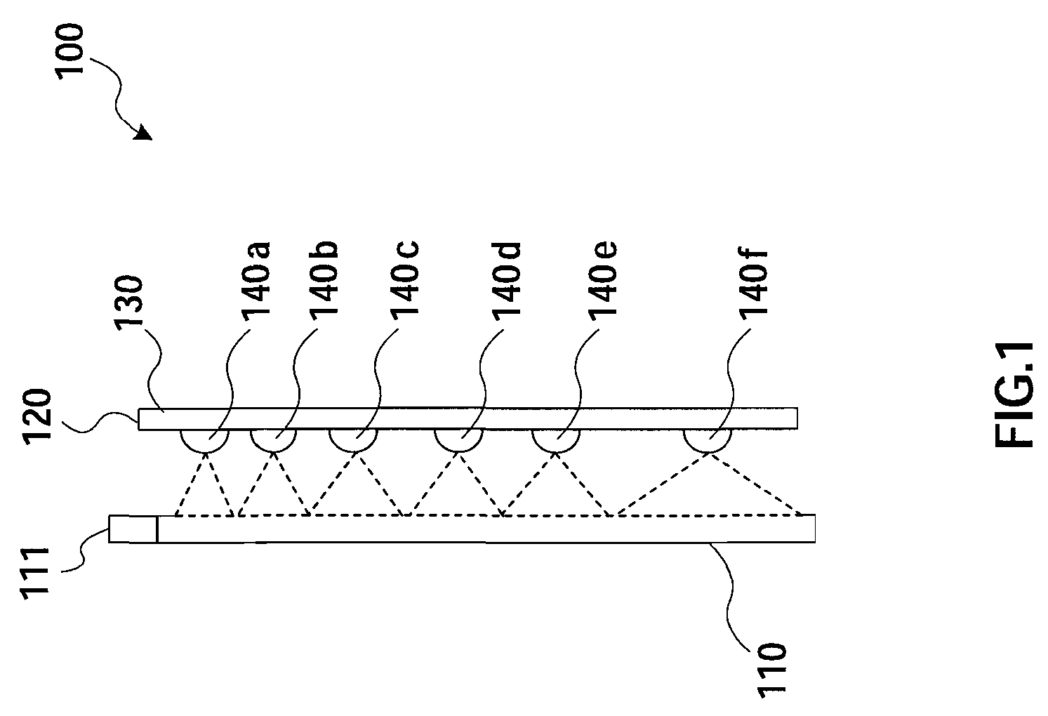
[0058]FIG. 1 is a side view of the principal parts of a liquid crystal display apparatus according to Embodiment 1 of the present invention.

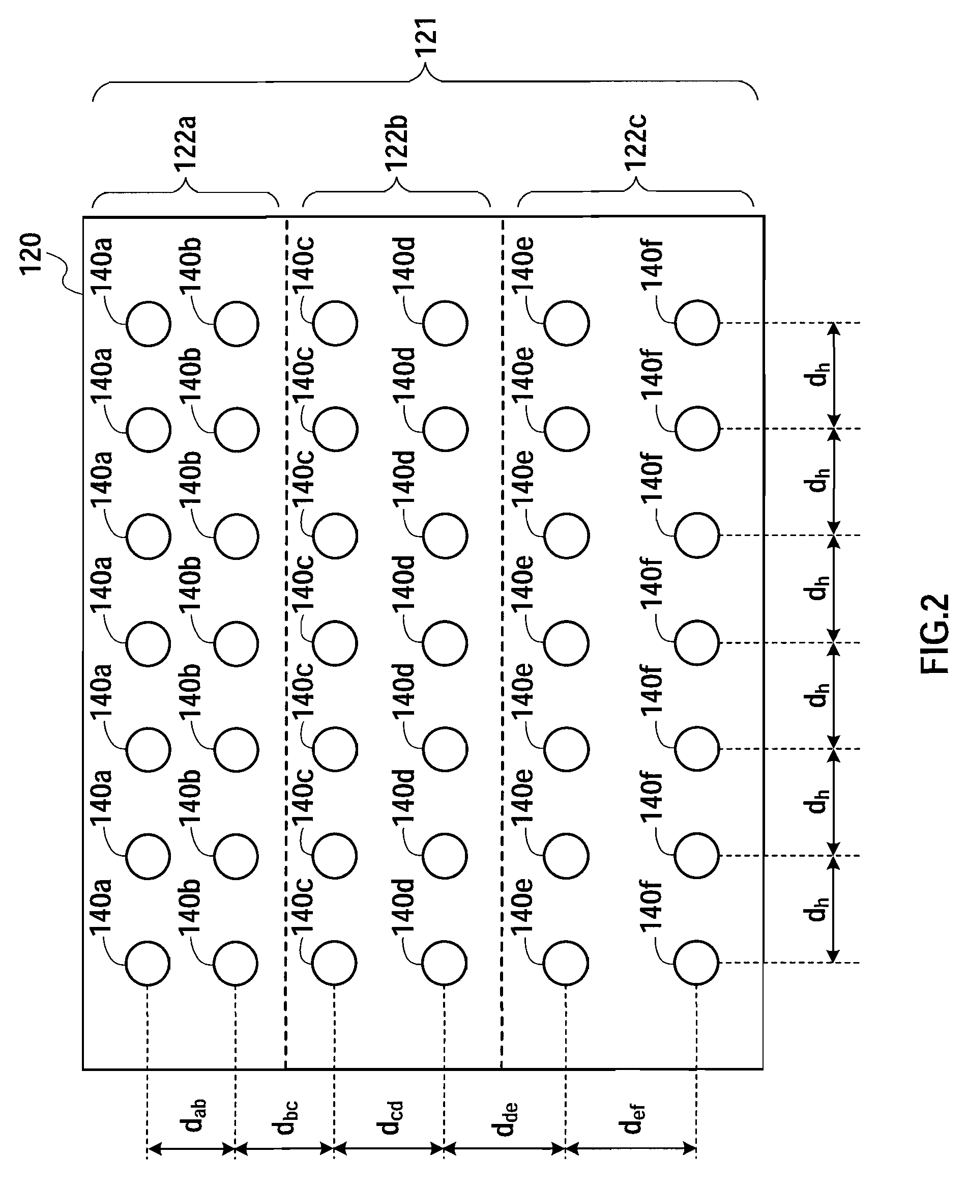
[0059]Liquid crystal display apparatus 100 has liquid crystal panel 110, liquid crystal driver 111, and LED backlight 120 as main components.

[0060]Liquid crystal panel 110 is a transmissive or semi-transmissive liquid crystal panel. Liquid crystal panel 110 transmits light emitted from LED backlight 120, and emits this transmitted light from the front surface of the display screen.

[0061]Liquid crystal driver 111 is placed in proximity to the upper edge of liquid crystal panel 110. In the descriptions of all the embodiments, “upper” means upper in the vertical direction of the display screen (hereinafter referred to simply as “vertical direction”) and in FIG. 1 corresponds to the top of the drawing in the vertical direction.

[0062]Liquid crystal driver 111 controls a drive voltage that drives liquid crystal panel 110 based on a video signal that i...

embodiment 2

[0110]FIG. 6 is a side view of the principal parts of a liquid crystal display apparatus according to Embodiment 2 of the present invention. Configuration elements identical to those in Embodiment 1 are assigned the same reference codes as in Embodiment 1, and detailed descriptions thereof are omitted here.

[0111]This embodiment differs from Embodiment 1 in the LED placement scheme.

[0112]Liquid crystal display apparatus 200 has liquid crystal panel 110, liquid crystal driver 111, and LED backlight 220 as main components.

[0113]LED backlight 220 has substrate 230 placed on the rear surface side of liquid crystal panel 110. The surface of substrate 230 is an opposed section opposite the rear surface of liquid crystal panel 110, and LEDs 240a, 240b, 240c, 240d, 240e, and 240f are arrayed on this surface in approximately flat form facing the rear surface of liquid crystal panel 110. That is to say, LED backlight 220 is a subjacent type of backlight apparatus.

[0114]Generally, a subjacent t...

embodiment 3

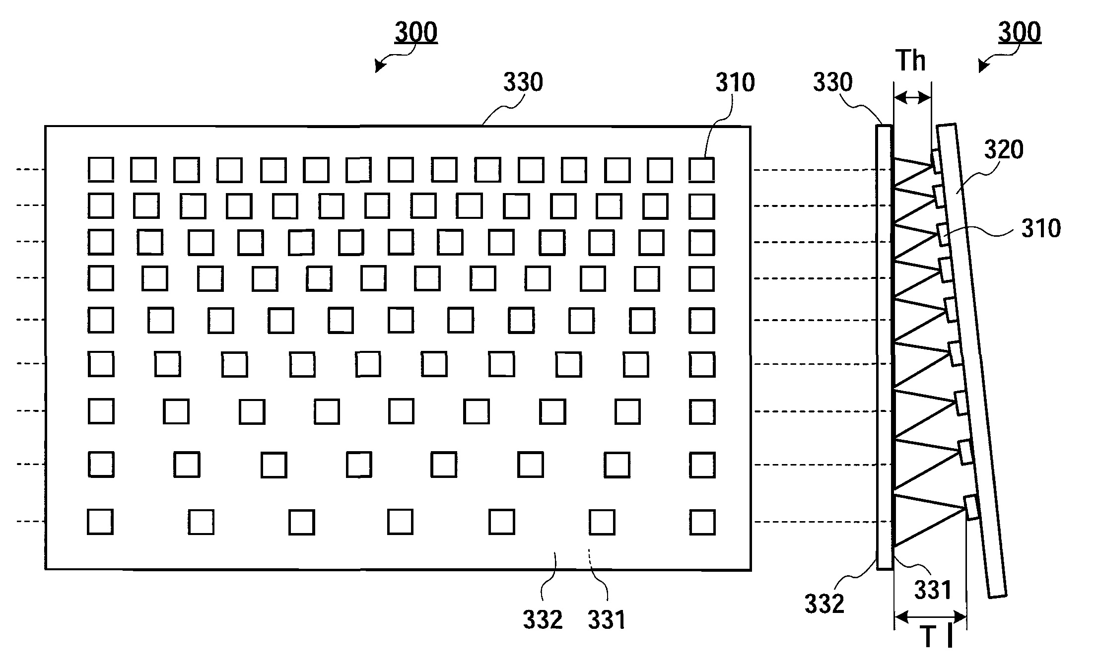
[0149]FIG. 10A and FIG. 10B are drawings showing the configuration of an LED backlight (backlight apparatus) according to Embodiment 3 of the present invention. FIG. 10A is a schematic front view of the LED backlight, and FIG. 10B is a schematic side view of the LED backlight. This embodiment relates, for example, to an LED backlight that is used as a liquid crystal display backlight and is configured so that brightness at the top of the screen is made particularly high when the liquid crystal display is set up so that the screen is vertical. A vertical direction in FIG. 10A and FIG. 10B corresponds to a vertical direction when the liquid crystal display apparatus in which the LED backlight is used is set up—that is, the vertical direction of the screen.

[0150]In FIG. 10A and FIG. 10B, LED backlight 300 has a plurality of LEDs 310, substrate 320 on which plurality of LEDs 310 are placed, and diffuser plate 330 placed on the light emitting side of LEDs 310, as main components. A plura...


PUM

PropertyMeasurementUnit
currentaaaaaaaaaa
temperatureaaaaaaaaaa

Abstract

A backlight apparatus is provided that enables a balance of brightness to be maintained over the entire area of a display screen and long life to be achieved. The surface of substrate 130 is opposite the rear surface of liquid crystal panel 110. LEDs 140 are placed on the surface of substrate 130. LED drive circuits 150 supply LEDs 140 with a current that causes LEDs 140 to emit light that illuminates liquid crystal panel 110. LED drive circuits 150 supply a lower current to LEDs 140 placed in an area having a higher ambient temperature within the surface area of substrate 130.

Description

CROSS REFERENCE TO RELATED APPLICATIONS[0001]The disclosures of Japanese Patent Application No. 2008-194048 filed on Jul. 28, 2008, No. 2008-214429 filed on Aug. 22, 2008, and No. 2008-214430 filed on Aug. 22, 2008, including the specifications, drawings and abstracts are incorporated herein by reference in their entirety.BACKGROUND[0002]1. Technical Field[0003]The technical field relates to a backlight apparatus and liquid crystal display apparatus, and more particularly to an LED (light emitting diode) backlight apparatus in which a plurality of LEDs are placed and a liquid crystal display apparatus having this.[0004]2. Description of the Related Art[0005]There is one kind of liquid crystal display apparatus that illuminates a liquid crystal panel using an LED backlight apparatus (hereinafter referred to simply as “LED backlight”).[0006]Unexamined Japanese Patent Publication No. 2007-165632 describes an example of a conventional liquid crystal display apparatus that has an LED bac...

Claims


Application Information

Patent Timeline
Patent Type & Authority Patents(United States)
IPC IPC(8): G02F1/1335
CPCG02F1/133603G09G3/3426G02F1/133611G02F2001/133613G09G3/3611G09G2320/0233G09G2320/041G09G2320/043G09G2320/0633G02F1/133613
Inventor KOBAYASHI, TAKAHIROYOSHIKAWA, MOTONOBUNISHIKOJI, YUICHI
Owner PANASONIC CORP
Why Eureka
Try Eureka