Positioning assembly for a bicycle lock

a technology for positioning assembly and bicycle locks, which is applied in the field of positioning assembly, can solve the problems of inconvenient use and operation of conventional positioning assembly

Active Publication Date: 2011-12-27
KUO LAMBERT
View PDF16 Cites 22 Cited by
  • Summary
  • Abstract
  • Description
  • Claims
  • Application Information

AI Technical Summary

Benefits of technology

The primary objective of the present invention is to provide a positioning assembly for a bicycle lock to adjust the direction of the bicycle lock conveniently.

Problems solved by technology

Therefore, the conventional positioning assembly is inconvenient in use and operation.

Method used


Image

  • Positioning assembly for a bicycle lock
  • Positioning assembly for a bicycle lock
  • Positioning assembly for a bicycle lock

Examples


Embodiment Construction

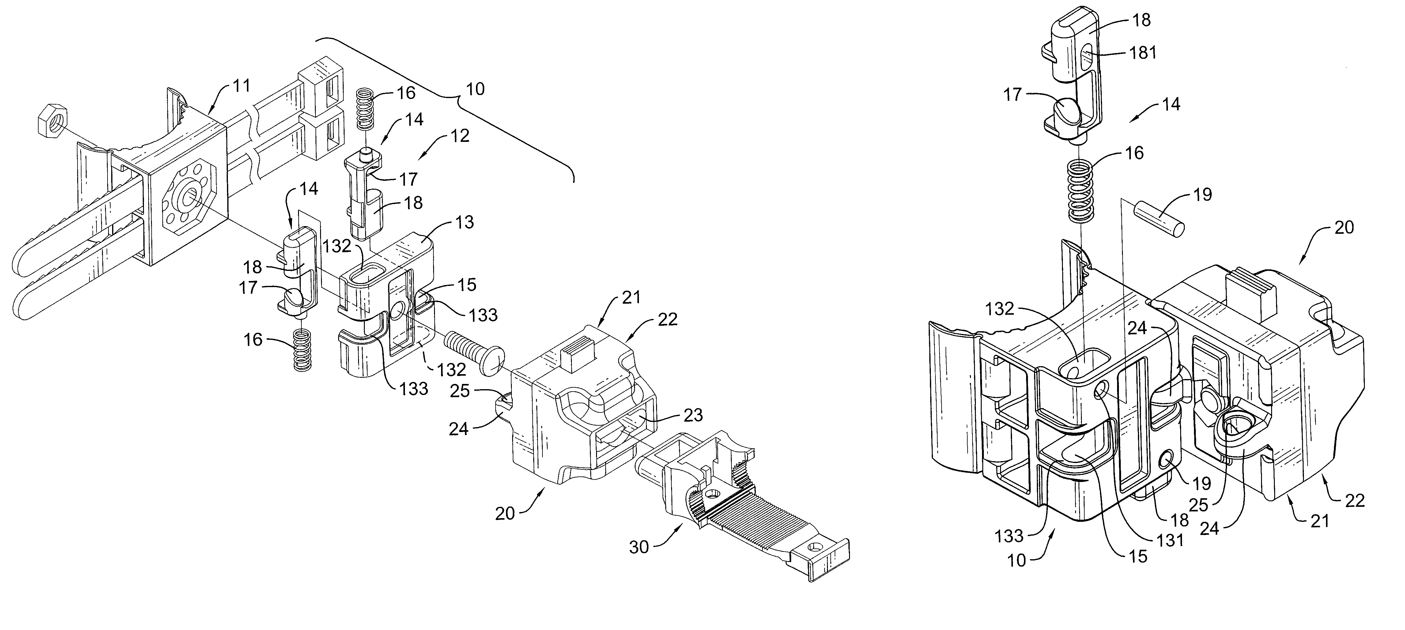
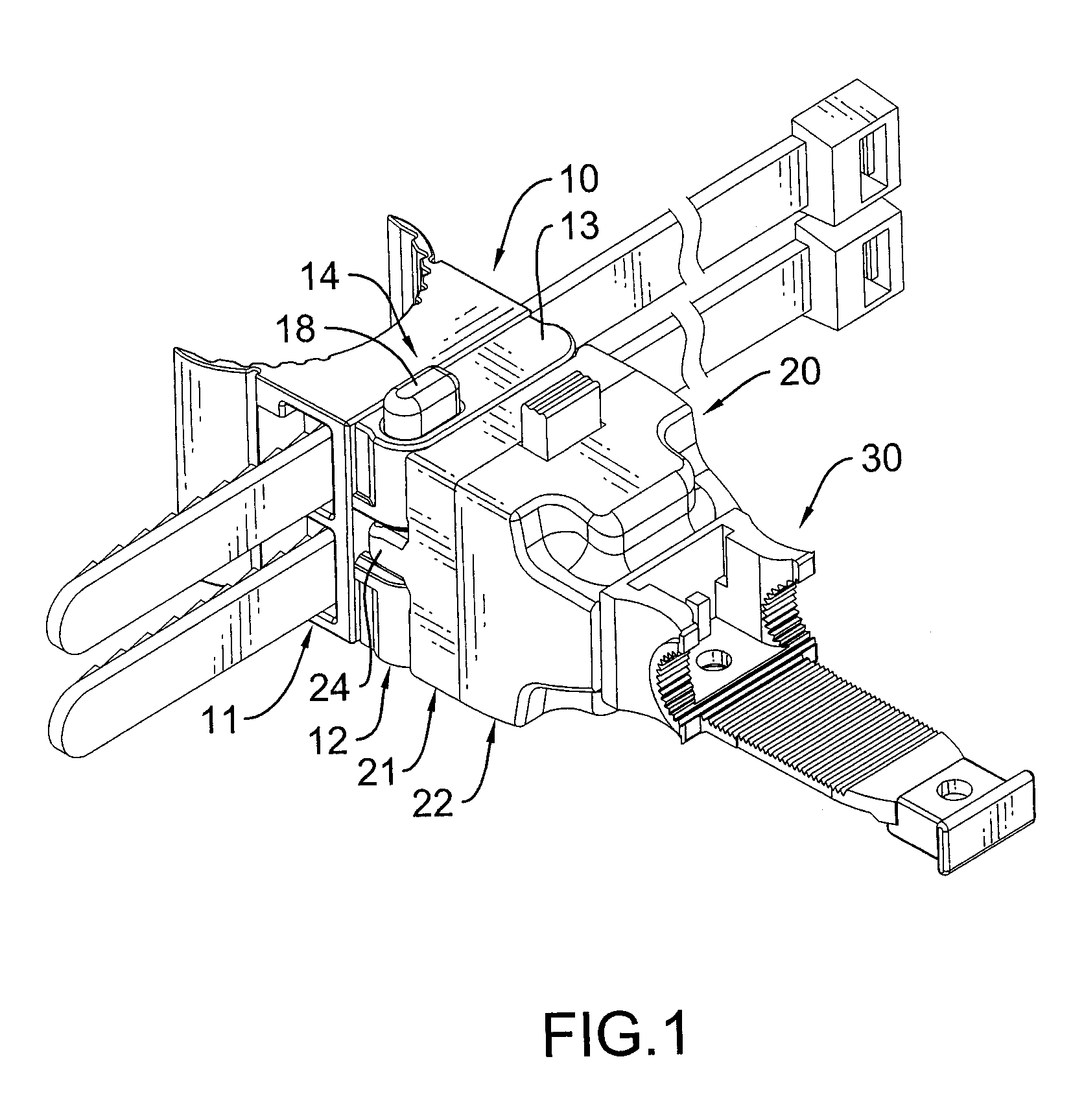
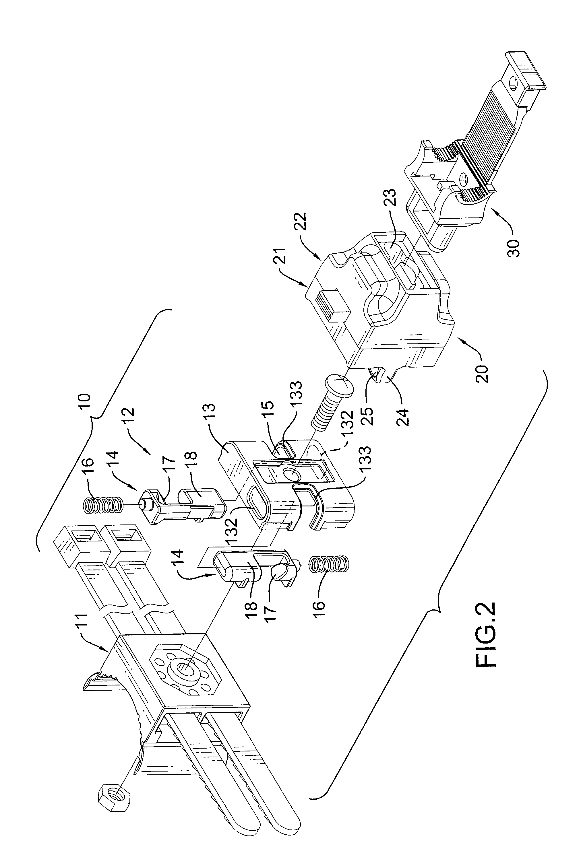
With reference to FIGS. 1, 2, 6, 7 and 8, a positioning assembly for a bicycle lock in accordance with the present invention has a positioning frame (10), a turning connector (20) and a linking element (30).

The positioning frame (10) is detachably mounted on a bicycle and has a mounting segment (11) and a controlling segment (12).

The mounting segment (11) is detachably mounted around a frame tube of the bicycle and has a front side and a rear side. The mounting segment (11) may have a belt mounted on the rear side and mounted around the frame tube or may have a C-shaped clamp formed on the front side and mounted around the frame tube of the bicycle by a fastener as shown in FIG. 7.

The controlling segment (12) is mounted or formed on the mounting segment (11) opposite to the belt or the clamp and has a base (13) and two pressing devices (14).

The base (13) may be mounted detachably on the rear side of the mounting segment (11) by a bolt and nut or may be formed on the rear side of the...


PUM


Abstract

A positioning assembly for a bicycle lock has a positioning frame, a turning connector and a linking element. The positioning frame is detachably mounted on a bicycle and has a mounting segment and a controlling segment. The controlling segment is mounted on the mounting segment and has a base and two pressing devices. The base has two mounting recesses. The pressing devices are movably and respectively mounted in the mounting recesses of the base. The turning connector is pivotally and detachably connected to the positioning frame and has a pivotal segment and a linking segment. The pivotal segment has two engaging elements mounted in the mounting recesses of the base to engage the pressing devices. The linking segment is formed with the pivotal segment and has an inserting hole. The linking element is detachably connected to inserting hole of the turning connector.

Description

BACKGROUND OF THE INVENTION1. Field of the InventionThe present invention relates to a positioning assembly, and more particularly to a positioning assembly for a bicycle lock to adjust the direction of the bicycle lock conveniently.2. Description of Related ArtA bicycle lock can be used to prevent a bicycle from being stolen, and can be mounted on the bicycle with a conventional positioning assembly.With reference FIG. 11, the conventional positioning assembly is detachably mounted on the bicycle and has a positioning frame (90) and a linking element (91). The positioning frame (90) is detachably mounted on a frame tube of the bicycle and has a front end, a rear end, a mounting segment (92) and a linking segment (93). The mounting segment (92) is formed on the front end of the positioning frame (90) and is mounted around the frame tube of the bicycle. The linking segment (93) is formed on the rear end of the positioning frame (90) and has a rear end and a linking recess. The linkin...

Claims


Application Information

Patent Timeline
Patent Type & Authority Patents(United States)
IPC IPC(8): B62J7/00B62J11/00B60R7/00B62H5/00
CPCB62H5/00B62J11/00E05B67/38E05B2067/386Y10S224/935Y10T70/5872Y10T70/8973
Inventor KUO, LAMBERT
Owner KUO LAMBERT
Why Eureka
Try Eureka