Training machine of load force simulation

a load force simulation and training machine technology, applied in the field of load force simulation training machines, can solve the problems of hurting the operator c, etc., and achieve the effects of saving the effo, small volume, and less nois

Active Publication Date: 2015-10-01
PROTUG
View PDF13 Cites 7 Cited by
  • Summary
  • Abstract
  • Description
  • Claims
  • Application Information

AI Technical Summary

Benefits of technology

[0020]With structures disclosed above, the present invention has the pulley system for loading to equally bear the load force and save the efforts fo r operation; on the other hand, it has the damping unit for retarding the strong retrieving force of the rope to ensure more safety. By having the damping force from the damping unit to elevate and lower the pulley system, the present invention has features of small volumes, less noises, and no restrictions of setting areas. In addition, the operation interface is able to adjust the load force directly, featuring more conveniences and no interruption during operation.

Problems solved by technology

Besides, when the operators C are decreasing the pulling force, the loading of the rope 13 would drop suddenly and cause a sudden winding of the rope winder 12 which may hurt the operators C.
However, there is only the second pulley 22 bearing the load force from the rope 26 and the resistant gravity of the weight blocks 25, causing it more efforts in operating; and when the operators C suddenly decrease the pulling force, the loading of the rope 26 would also decrease suddenly and cause a sudden dropping of the weight blocks 25 which may hurt the operators C.
However, there is only the pulley assembly 32 bearing the load force from the tug of war rope 33 and the resistant gravity of the weight blocks 34, causing it more efforts in operating; and when an operator C suddenly decreases the pulling force, the loading of the tug of war rope 33 would also decrease suddenly and cause a sudden dropping of the weight blocks 34 which may hurt the operator C.
However, there is only the pulley set 32A bearing the load force from the pull down bar 33A and the resistant gravity of the weight blocks 34A, causing it more efforts in operating; and when an operator C suddenly decreases the pulling force, the loading of the tug of war rope 33A would also decrease suddenly and cause a sudden dropping of the weight blocks 34A which may hurt the operator C.
1. The rope winder 12, second pulley 22, pulley assembly 32, and pulley set 32A are the components bearing the loading, but when they are bearing too much loading, it would cause much more efforts in the operation process and the components tend to be damaged more easily.
2. The driving components of complex decelerating machine 11 and the weight blocks 25, 34, 34A with large volumes have problems of space occupation, high noises, and restrictions of setting area due to the need of electricity. On the other hand, when the operators decreases the pulling force in a sudden or does not have enough strength to pull, the rope 13, 26, tug of war rope 33, and pull down bar 33A would have strong retrieving force that may hurt the operators.
3. The weight blocks 25, 34, 34A on the training machines have to be increased or decreased piece by piece, causing inconveniences for the operators and interruptions in the training process.

Method used


Image

  • Training machine of load force simulation
  • Training machine of load force simulation
  • Training machine of load force simulation

Examples


Embodiment Construction

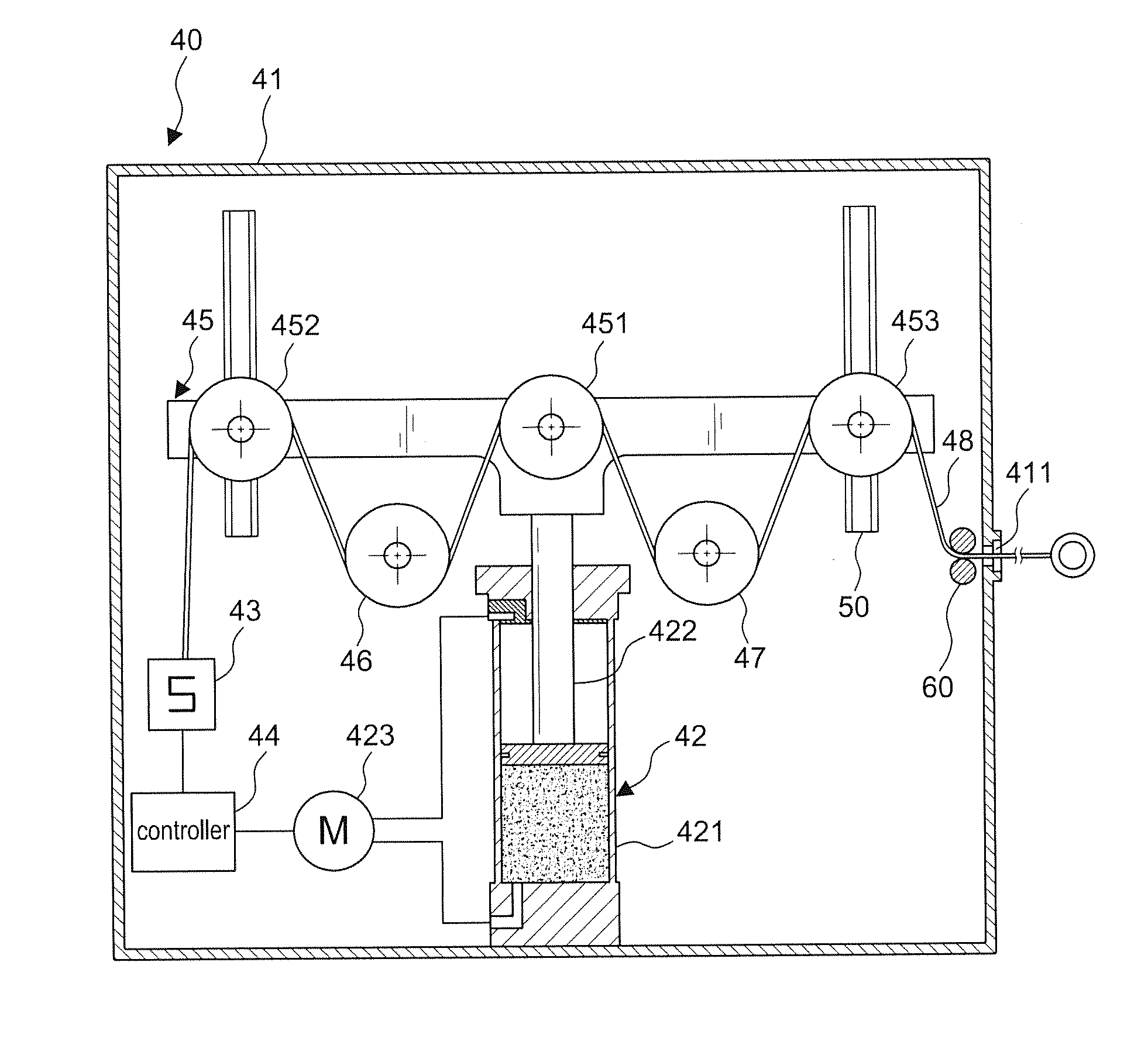
[0033]Referring to FIGS. 4-9, in a preferred embodiment, the present invention comprises a housing 41, a damping unit 42, a load cell 43, a controller 44, a pulley system 45, at least one left fixed pulley 46, at least one right fixed pulley 47, a steel rope 48, and a rope 49.

[0034]The damping unit 42 is disposed inside the housing 41 and comprises a press cylinder including a cylinder 421, a movable piston rod 422, and a pressure source 423 to elevate the piston rod; in this embodiment, the press cylinder comprises either a hydraulic cylinder or a pneumatic cylinder.

[0035]The load cell 43 is disposed inside the housing 41. The controller 44 is coupled to the pressure source 423 of the damping unit 42 and the load cell 43 in order to calculate the load value set by the load cell 43 so that when the load value is beyond the allowable range, a signal would be transmitted back to the controller 44 to control the damping force; in this embodiment, the present invention can be a large ma...


PUM


Abstract

A training machine of load force simulation has a damping unit comprises a press cylinder which includes a cylinder, a movable piston rod, and a press source; a controller is coupled to the press source of the damping unit and a load cell for calculating and controlling the load value of the load cell, allowing the elevating and lowering of a pulley system thereof by adjusting the damping force via the piston rod. Also, the pulley system comprises a plurality of movable pulleys to equally bear the load force from the rope, saving the efforts for operating and retarding the retrieving force of the rope for safety. The present invention is therefore able to replace complex decelerating machines and massive weight blocks in apparatus suchlike with features of small volumes as less space needed, less noises, and no restrictions of setting areas due to no need of electricity. Furthermore, it comprises an operation interface for direct controlling of the load force, featuring more conveniences and no interruption when practicing the operation.

Description

BACKGROUND OF THE INVENTION[0001]1. Field of the Invention[0002]The present invention relates to a training machine of load force simulation, particularly to one that can simulate the load force by a controller to conduct a tug of war practice with the operator to achieve the purpose of fitness training and that has a plurality of movable pulleys to equally bear the load force, achieving an effort-saving feature; when the operator releases less force, the present invention can also automatically control the corresponding damping force, retarding the load force and avoiding injuries to the operator and therefore achieving a safe feature.[0003]2. Description of the Related Art[0004]FIGS. 1, 2, 3, and 3A are different kinds of fitness training machines invented for variables such as the number of operators, places for operation, and weight levels; it is further illustrated the simulation of load force, the mode of practicing, and the structure of providing stable load force in each fig...

Claims


Application Information

Patent Timeline
Patent Type & Authority Applications(United States)
IPC IPC(8): A63B21/00
CPCA63B21/00007A63B21/00036A63B71/0054A63B21/153A63B21/156A63B21/285A63B23/03575A63B23/1209A63B24/0087A63B2024/0093A63B2071/0063A63B2071/0658A63B2220/51A63B21/151A63B21/158
Inventor HUANG, JUI-TUNG
Owner PROTUG
Why Eureka
Try Eureka