Pair of ophthalmic eyeglasses and a method of forming an engagement peripheral ridge on the edge face of a lens

a technology of ophthalmic eyeglasses and peripheral ridges, which is applied in the field of mounting ophthalmic lenses, can solve the problems of affecting the quality and accuracy of the lens mounting frame, affecting the appearance, and affecting the appearance of the eyeglasses

Active Publication Date: 2011-12-27
ESSILOR INT CIE GEN DOPTIQUE
View PDF11 Cites 6 Cited by
  • Summary
  • Abstract
  • Description
  • Claims
  • Application Information

AI Technical Summary

Benefits of technology

[0016]As a result there is no visible space between the inside of the rim and the front face of the lens, and the rim of the frame is thus mounted flush with the front face of the lens. This improves the appearance of the mounting.
[0048]The use of a small-diameter tool for implementing the method of the invention makes it possible, when the lens presents a risk of the peripheral ridge being pared away, to form the peripheral ridge, while limiting the extent to which it is pared away.

Problems solved by technology

Furthermore, for strongly cambered lenses that are beveled using a finishing grindwheel including a ridging groove, it is found that the bevel becomes partially pared away: it becomes thinner on the strongly cambered portions of the edge face of the lens.
This thinning of the bevel degrades the quality and the accuracy with which the lens is mounted in the frame.
There thus exists a certain amount of space that remains visible between the rim of the frame end the front face of the lens, which is unattractive in appearance and tends to collect dirt.

Method used


Image

  • Pair of ophthalmic eyeglasses and a method of forming an engagement peripheral ridge on the edge face of a lens
  • Pair of ophthalmic eyeglasses and a method of forming an engagement peripheral ridge on the edge face of a lens
  • Pair of ophthalmic eyeglasses and a method of forming an engagement peripheral ridge on the edge face of a lens

Examples


first embodiment

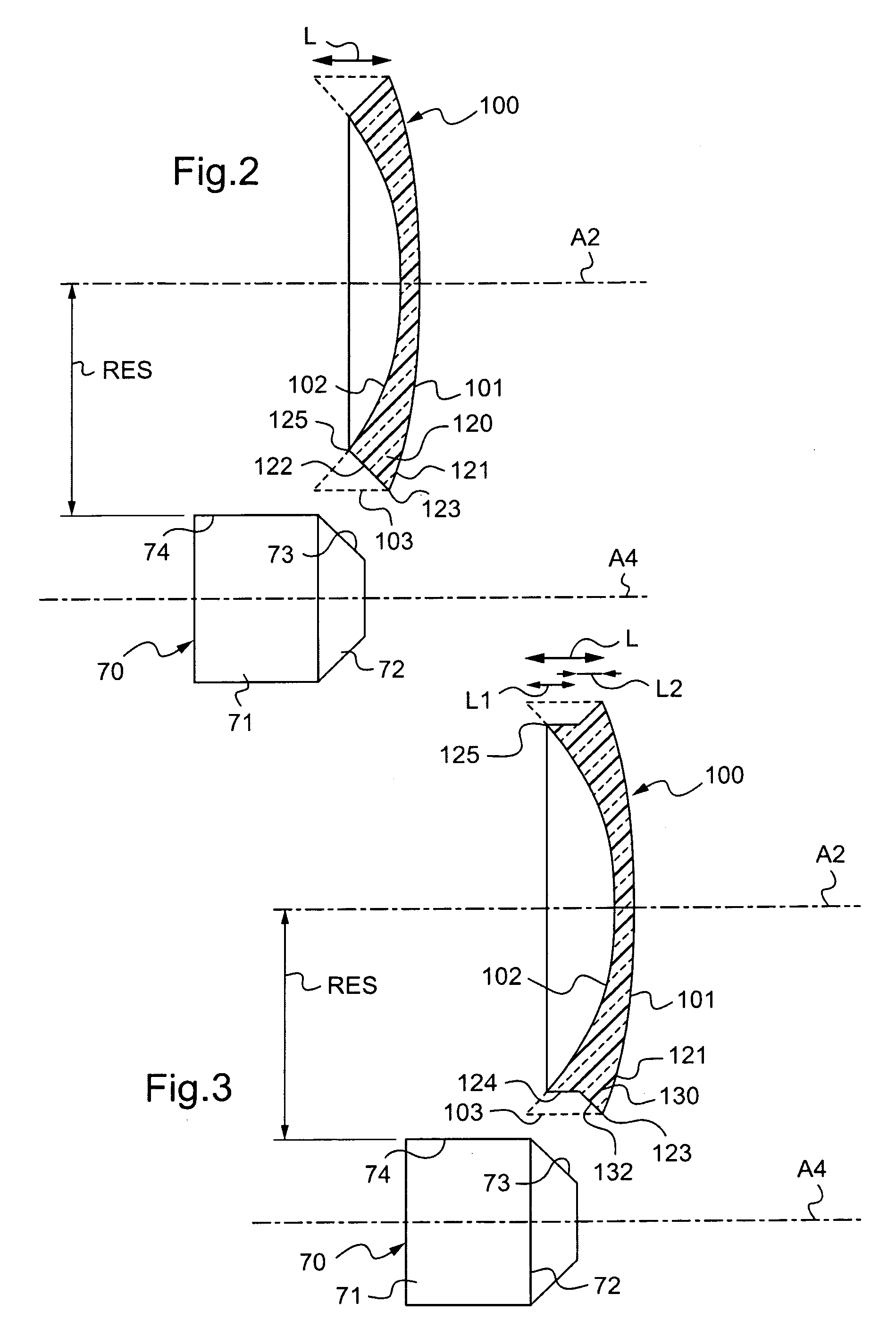
[0055]FIG. 2 is a side view of a lens and of a machining tool driven to form a peripheral ridge on the edge face of the lens in a first embodiment;

second embodiment

[0056]FIG. 3 is a side view of the lens and the machining tool driven to form a peripheral ridge on the edge face of the lens in a second embodiment;

[0057]FIG. 4 is a view of the FIG. 2 lens mounted in a rim an eyeglass frame;

[0058]FIG. 5 is a view of the FIG. 3 lens mounted in a rim of an eyeglass frame; and

third embodiment

[0059]FIG. 6 is a side view of the lens and another machining tool driven to machine the front flank of the peripheral ridge in a

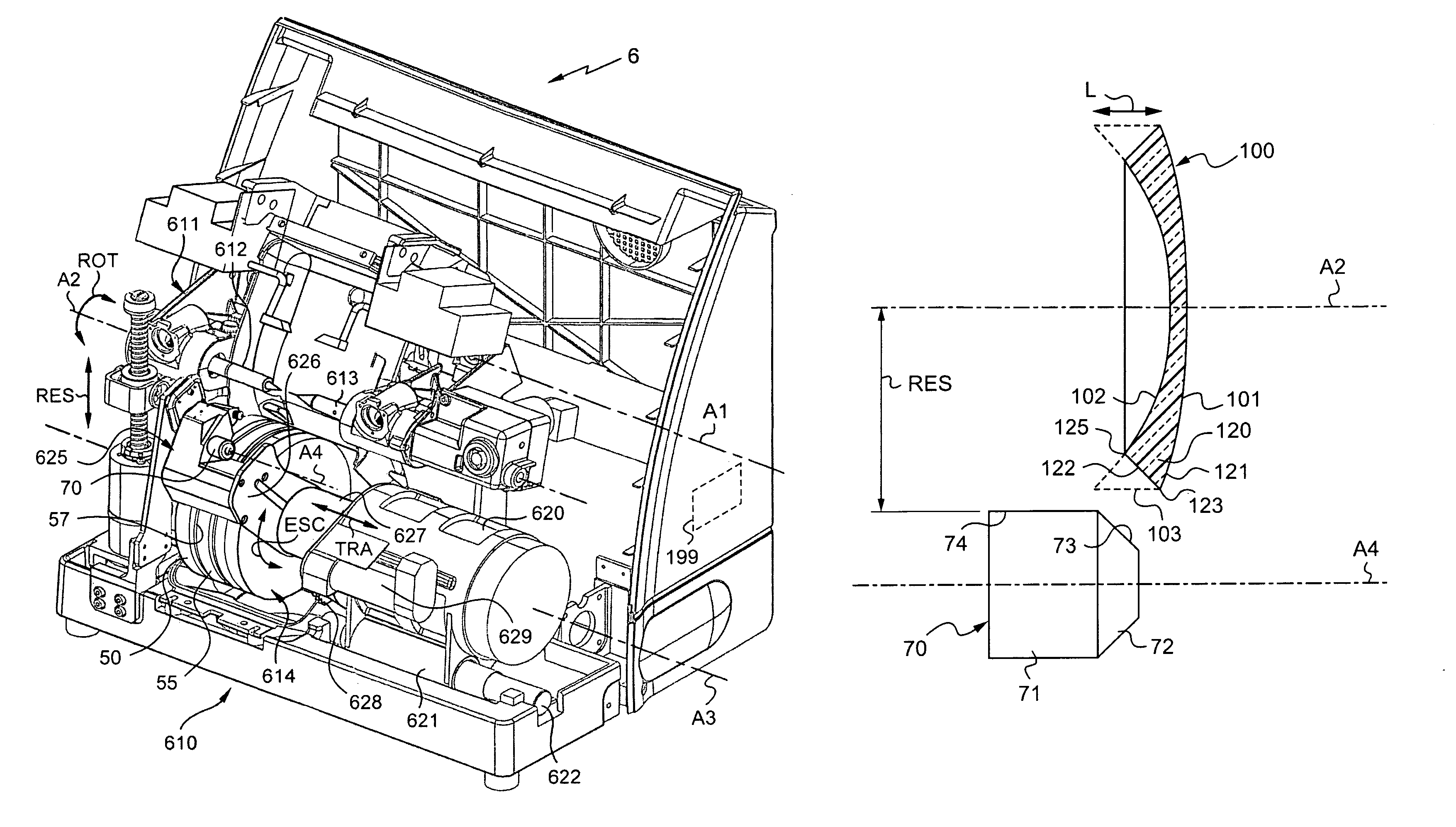
[0060]Firstly it is recalled that an ophthalmic lens 100 possesses a convex front face 101 and a concave rear face 102, together with an edge face 103 and front and rear edges 123 and 125 at the junctions between the edge face 103 and the front and rear faces 101 and 102 (see FIGS. 2 and 3).

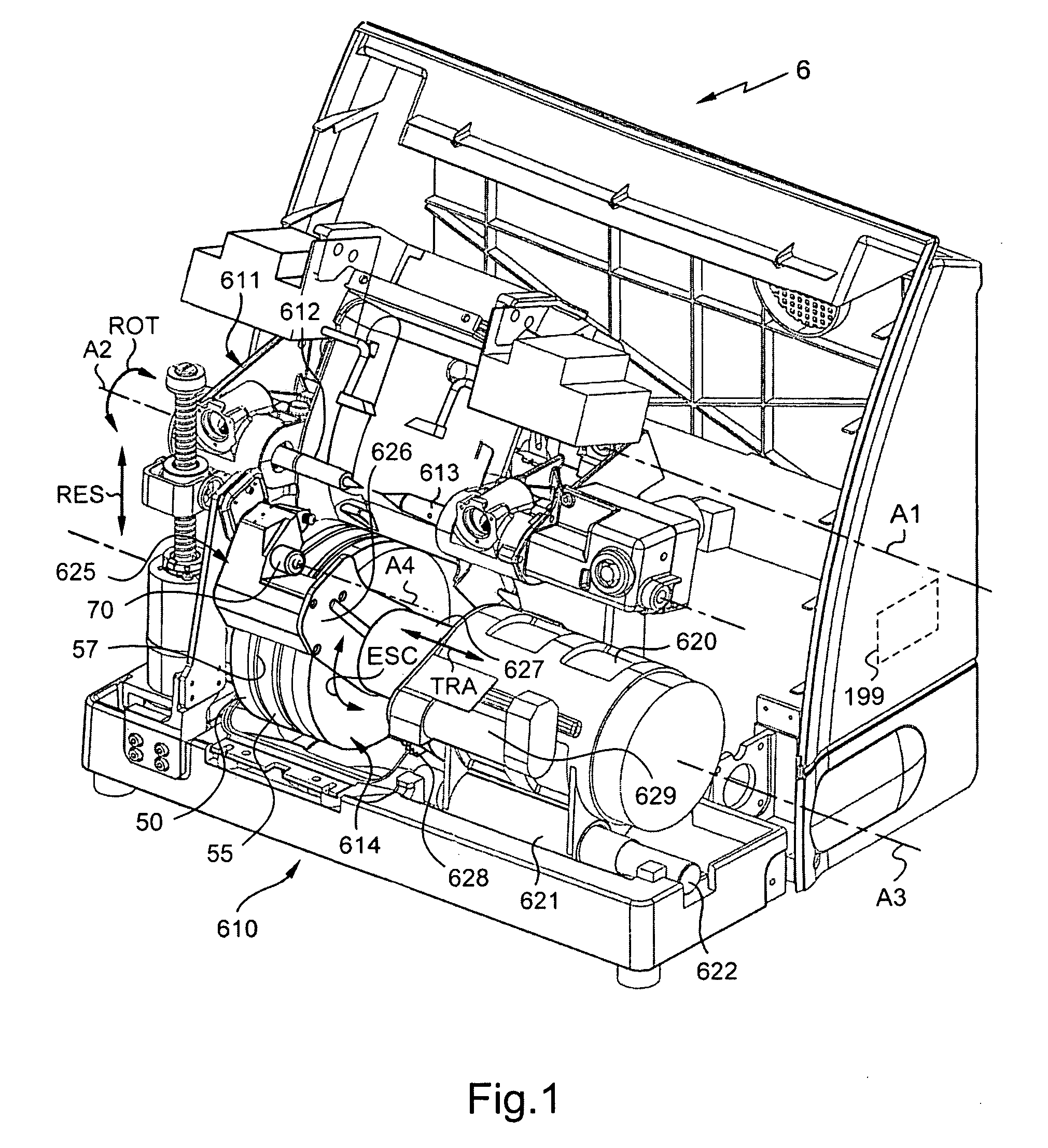
[0061]FIG. 1 shows a numerically controlled shaper device 6 adapted to modify the outline of the ophthalmic lens in order to fit it into the rim of a selected frame.

[0062]The device includes a rocker 611 that is mounted to pivot freely about a first axis A1, in practice a horizontal axis, on a frame. In order to drive an ophthalmic lens for machining in rotation, and in order to prevent it from moving, the rocker 611 is provided with support means suitable for clamping on the ophthalmic lens 100 and for driving it. These support means, or holder means, comprise two clam...


PUM

PropertyMeasurementUnit
radiusaaaaaaaaaa
diameteraaaaaaaaaa
thicknessaaaaaaaaaa

Abstract

A pair of eyeglasses includes: a frame provided with at least one rim presenting an internal bezel; and a lens mounted in the frame, the lens presenting a front face, a rear face, and on its edge face, an engagement peripheral ridge presenting a rear flank, situated beside the rear face of the lens and a front flank situated beside the front face of the lens, the front and rear flanks being engaged in the internal bezel. The front flank of the engagement peripheral ridge presents continuity of at least first order with the remainder of the front face. The edge face of the lens presents a rear shoulder or foot, and in that the radial height of the engagement peripheral ridge considered between the peak of the peripheral ridge and the foot varies along the periphery of the lens.

Description

TECHNICAL FIELD TO WHICH THE INVENTION RELATES[0001]The present invention relates in general to mounting ophthalmic lenses of a pair of ophthalmic eyeglasses in a frame, and it relates more particularly to engaging a lens in a surround of the frame of a pair of dark or correcting ophthalmic eyeglasses.TECHNOLOGICAL BACKGROUND[0002]As a general rule, a frame has rims each presenting an internal bezel forming a groove. The shaping of a lens in order to enable it to be mounted in the frame selected by the future wearer then consists in modifying the outline of the lens so as to match it to the frame.[0003]With lenses for frames having rims, the shaping of the lens includes a final step referred to as beveling (or ridging) that consists in forming a ridge, commonly referred to as a bevel, that is generally of triangular cross-section on the edge face of the ophthalmic lens. The bevel is for engaging in the bezel formed in the rim or surround of the eyeglass frame in which the lens is to...

Claims


Application Information

Patent Timeline
Patent Type & Authority Patents(United States)
IPC IPC(8): B24B1/00
CPCB24B9/148B24D7/02G02C1/06
Inventor NAUCHE, MICHEL
Owner ESSILOR INT CIE GEN DOPTIQUE
Why Eureka
Try Eureka