Leakage power reduction apparatus

a technology of leakage power and reduction apparatus, which is applied in the direction of electrical equipment, radio transmission, transmission control/equalization, etc., can solve the problems of small part of the reflected power distortion in the lna, power of the transmission signal leakage to the receiver side, etc., and achieve the effect of suppressing the leakage power and not lowering the power utilization efficiency

Inactive Publication Date: 2011-12-27
NTT DOCOMO INC
View PDF16 Cites 69 Cited by
  • Summary
  • Abstract
  • Description
  • Claims
  • Application Information

AI Technical Summary

Benefits of technology

[0016]Accordingly, an object of the present invention is to provide a leakage power reduction apparatus that can suppress leakage power from the transmitter side to the receiver side without lowering the power utilization efficiency, for use in communication equipment which performs communication by allocating two frequencies in adjacent frequency bands to transmission and reception.

Problems solved by technology

However, a very small part of the reflected power leaks to the receiver side.
If the power of the signal input to the antenna 30 is large and if the absolute value of the reflected power is large accordingly, the leakage power to the receiver side may cause distortion in the LNA.
The same problem occurs between the terminals #1 and #3, where the duplexer 120 is connected to the transmitter and the receiver, because a part of the power of the transmission signal leaks to the receiver side.
However, it is very difficult to adopt this approach if the transmission frequency is close to the reception frequency.
The power consumed by the amplifier inevitably lowers the power utilization efficiency of the apparatus.

Method used


Image

  • Leakage power reduction apparatus
  • Leakage power reduction apparatus
  • Leakage power reduction apparatus

Examples


first embodiment

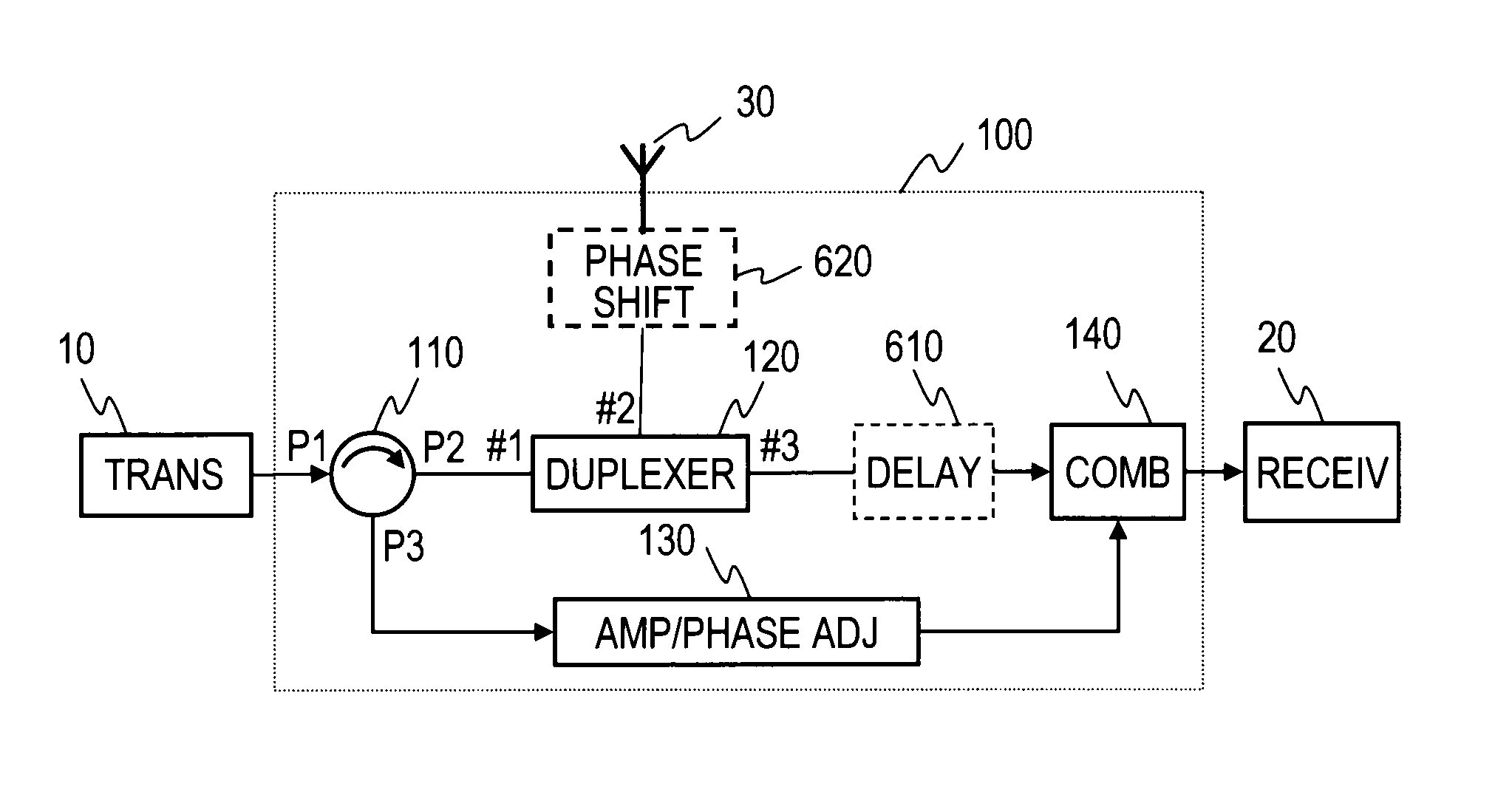
[0039]FIG. 1 shows a functional block diagram of a leakage power reduction apparatus 100 of the present invention. FIG. 11 is a flow chart of the corresponding processing.

[0040]The leakage power reduction apparatus 100 of the present invention includes a circulator 110, a duplexer 120, an amplitude-and-phase adjuster 130, and a combiner 140. The circulator 110 and the duplexer 120 are the same as those included in the structure described earlier with reference to FIG. 14. The combiner 140 is the same as that included in the apparatus described earlier with reference to FIG. 16.

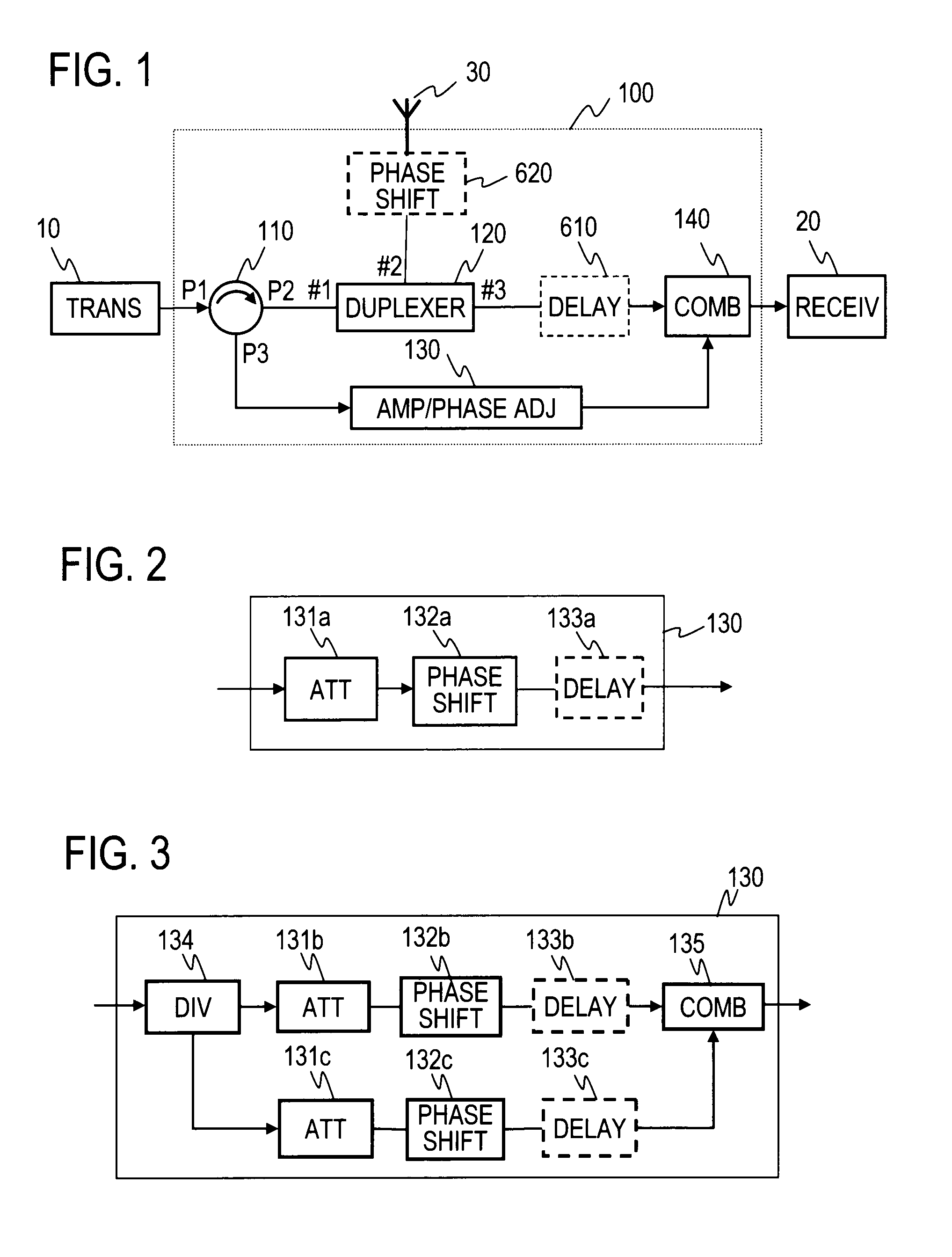
[0041]The amplitude-and-phase adjuster 130 is connected to a third port P3 of the circulator 110, generates an offset signal by adjusting the amplitude and phase of a signal input from the circulator 110, and gives the generated signal to the combiner 140.

[0042]The principle of operation of the first embodiment will be described next.

[0043]A transmission signal coming from a transmitter 10 passes through the c...

second embodiment

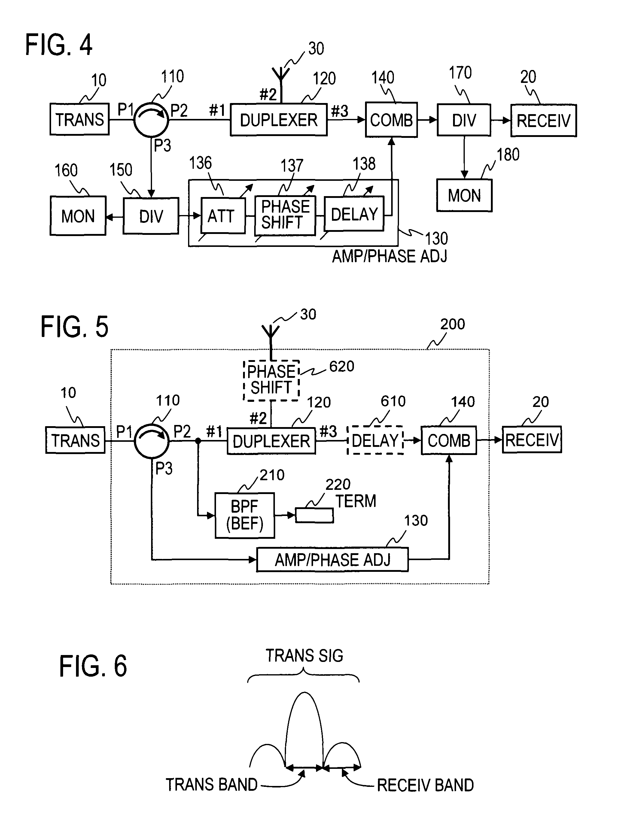
[0052]FIG. 5 is a functional block diagram showing an example structure of a leakage power reduction apparatus 200 of a second embodiment of the present invention.

[0053]The transmission signal from the transmitter 10 is usually a modulation signal and generally contains not only a component of the transmission frequency band but a component of the reception frequency band as distortion, as shown in FIG. 6. If the transmission signal contains a reception frequency band component, the structure of the first embodiment can prevent a transmission frequency band component of the transmission signal from leaking to the side of the receiver 20, as described earlier. However, a large part of the power of the reception frequency band component of the transmission signal input to the first terminal #1 of the duplexer 120 is rejected by the transmission band-pass filter 121 (see FIG. 15) in the duplexer 120. If the rejected signal passes through the circulator 110, the amplitude-and-phase adju...

third embodiment

[0058]FIG. 7 is a functional block diagram showing an example structure of a leakage power reduction apparatus 300 of a third embodiment of the present invention.

[0059]The third embodiment is structured by disposing an attenuator 310 and a reflector 320 instead of the terminator 220 in the structure of the second embodiment shown in FIG. 5. A circulator 110, a duplexer 120, an amplitude-and-phase adjuster 130, a combiner 140, and a reception band-pass filter 210 (BPF) have the same function as those corresponding elements used in the second embodiment.

[0060]The attenuator 310 is connected between the reception band-pass filter 210 (BPF) and the reflector 320 and attenuates the amplitude of an input signal. The reflector 320 is a transmission line having a certain length with an open end or a short-circuited end and reflects a signal input from the attenuator 310 back to the attenuator 310 again, adding a predetermined phase difference.

[0061]Most of the power of the reception frequen...


PUM


Abstract

A circulator extracts a transmission signal sent from a transmitter to antenna via the circulator and a duplexer, reflected by an antenna, and returned via the duplexer to the transmitter side. The amplitude and phase of the extracted signal are adjusted by an amplitude-and-phase adjuster to generate an offset signal having the same amplitude and the opposite phase with respect to a leaking transmission signal included in a signal output from a third terminal of the duplexer when combined by a combiner. The offset signal is combined in the combiner with the leaking transmission signal included in the signal output from the third terminal of the duplexer to suppress the leaking transmission signal.

Description

BACKGROUND OF THE INVENTION[0001]1. Field of the Invention[0002]The present invention relates to apparatuses for reducing power leaking from a transmitter side to a receiver side, for use in communication equipment which performs communication by allocating two frequencies in adjacent frequency bands to transmission and reception.[0003]2. Description of the Related Art[0004]In communication equipment which performs communication by allocating two frequencies in adjacent frequency bands to transmission (transmission frequency f1) and reception (reception frequency f2), a duplexer is provided to use an antenna for both transmission and reception, as shown in FIG. 14.[0005]The structure shown in FIG. 14 will be described. A transmitter 10 includes a power amplifier (PA) and outputs a transmission signal. A receiver 20 includes a low-noise amplifier (LNA) and detects a desired signal. An antenna 30 emits the transmission signal in the form of a radio wave into space and also catches a d...

Claims


Application Information

Patent Timeline
Patent Type & Authority Patents(United States)
IPC IPC(8): H04B1/04H04B1/40
CPCH04B1/525H04B1/52H04B1/18H04B1/50
Inventor FUKUDA, ATSUSHIOKAZAKI, HIROSHINARAHASHI, SHOICHI
Owner NTT DOCOMO INC
Why Eureka
Try Eureka