
Distributed multicast system and method in a network

Inactive Publication Date: 2011-12-27
EGENERA
View PDF27 Cites 31 Cited by
  • Summary
  • Abstract
  • Description
  • Claims
  • Application Information

AI Technical Summary

Benefits of technology

This approach enhances scalability and reliability by distributing the workload among multiple processor nodes, minimizing packet loss and latency, and allowing for efficient rerouting around unhealthy nodes, thus improving network performance.

Problems solved by technology

As such, because all multicast processing is in the control node scalability issues arise in certain contexts.

Method used


Image

  • Distributed multicast system and method in a network
  • Distributed multicast system and method in a network
  • Distributed multicast system and method in a network

Examples


Embodiment Construction

[0047]The embodiments of the invention provide multicast communication using a distributed approach. Processing nodes assist in distributing multicast packets to other members of the multicast group.

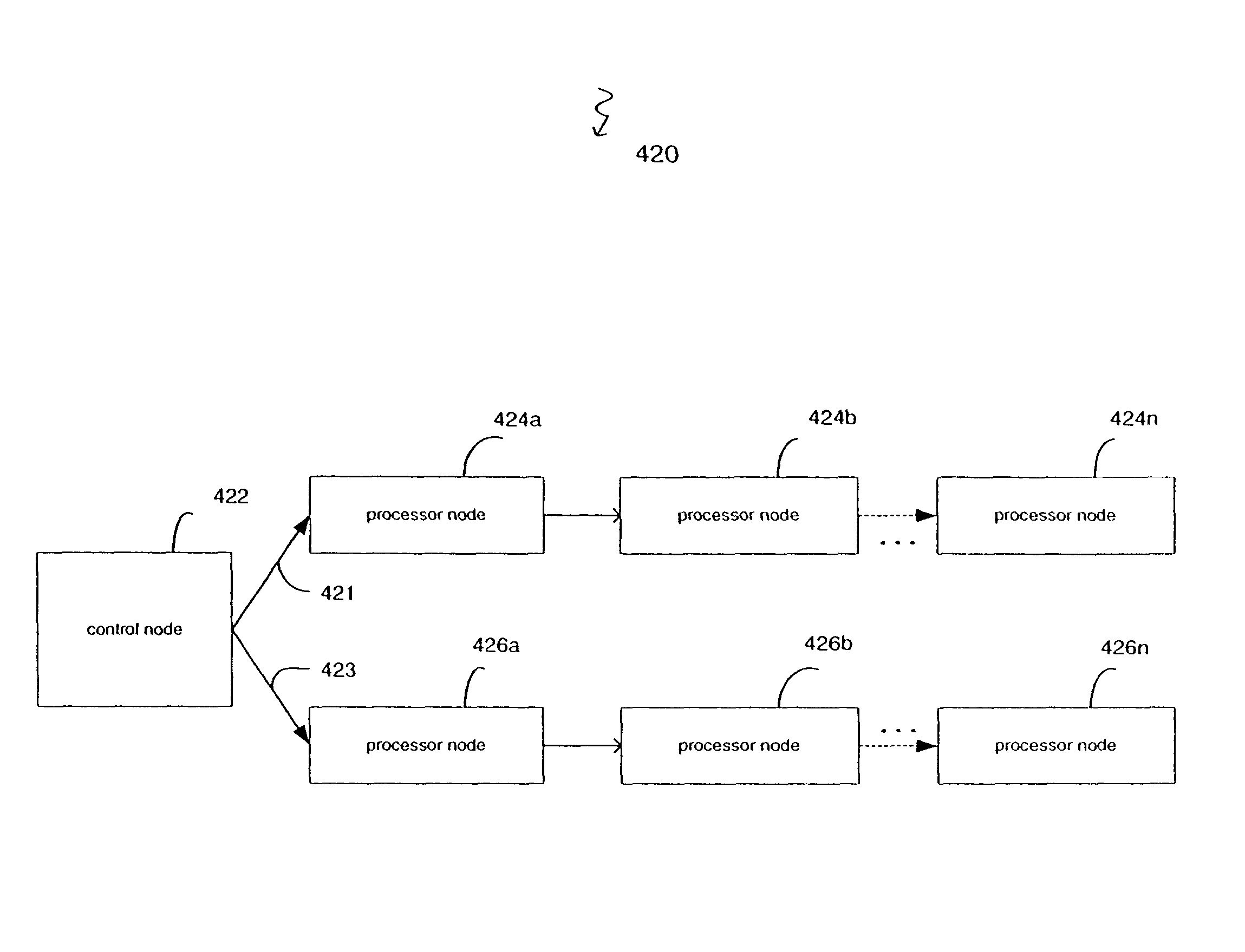
[0048]The multicast distribution methods of preferred embodiments use multicast distribution chain mechanisms. FIG. 4 illustrates a high-level model of the multicast distribution chains of certain embodiments. Multicast packets are delivered to the control node 422 but the control node 422 only sends the packet to the first processor node 424a, 426a on each of two multicast distribution chains 421, 423. These processor nodes 424a, 426a then each forward the packet to a respective subsequent processor node in the respective chain, for example, to the second processor nodes 424b, 426b, and so forth, until the multicast packet has been delivered to all necessary processor nodes in each chain.

[0049]Even though, FIG. 4 illustrates two chains, any number of chains can be provided. For example,...


PUM


Abstract

The invention provides multicast communication using distributed topologies in a network. The control nodes in the network build a distributed topology of processor nodes for providing multicast packet distribution. Multiple processor nodes in the network participate in the decisions regarding the forwarding of multicast packets as opposed to multicast communications being centralized in the control nodes.

Description

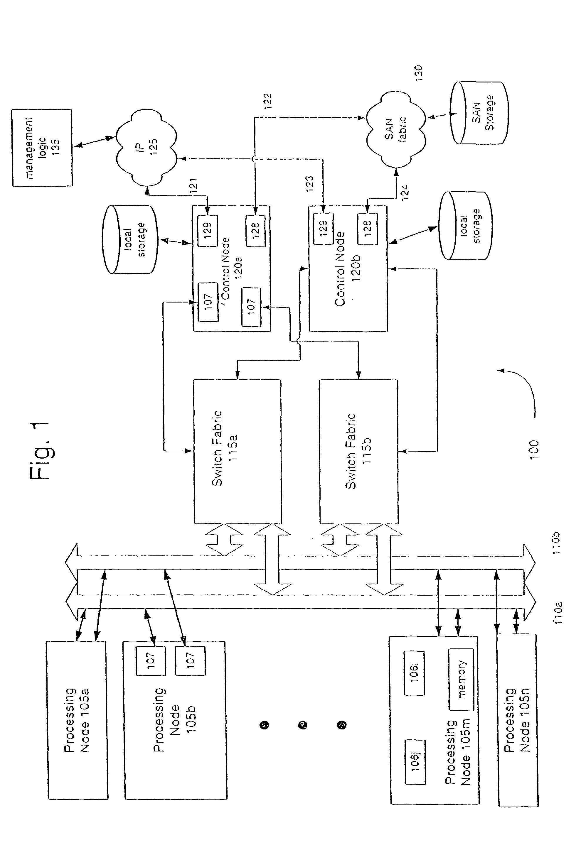
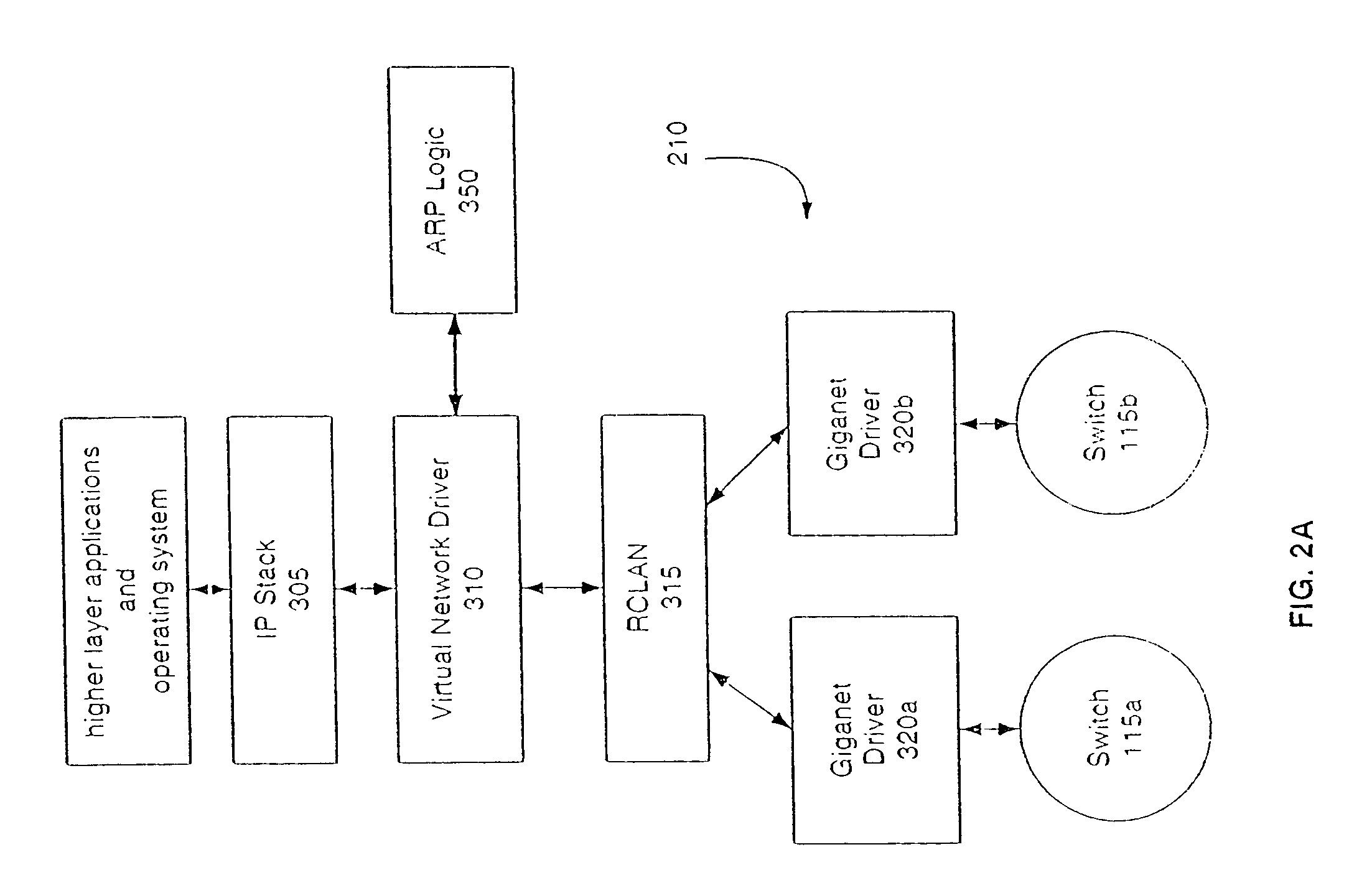
TECHNICAL FIELD[0001]This invention relates generally to emulating multicast functionality in communication networks.BACKGROUND[0002]Multicast functionality delivers a packet of network data to ideally all recipients registered in a multicast group. More specifically, a group of receivers register an interest in receiving a particular data stream. This group does not have any physical or geographical boundaries, i.e., the receivers can be located anywhere on the network.[0003]Multicast functionality can be directly supported by the network infrastructure or it may be emulated. For example, in the BladeFrame product by Egenera the multicast functionality is emulated.[0004]In the BladeFrame platform architecture, the communication mechanism is point-to-point and provided in a virtual interface (VI)-modeled switched Giganet fabric. Multicast functionality is emulated using a control node to distribute multicast packets to processor nodes. A single multicast packet is received by the co...

Claims


Application Information

Patent Timeline
Patent Type & Authority Patents(United States)
IPC IPC(8): G06F15/173G06F15/16H04L12/28
CPCH04L12/1854Y10S370/901Y10S370/912Y10S370/902Y10S370/908Y10S370/909
Inventor DUFFY, IV, EDWARD T.GENG, SCOTT M.HUANG, HAIQIN, HUA
Owner EGENERA
Learn More