Updating frame divisions based on ray tracing image processing system performance

a ray tracing and image processing technology, applied in the field of computer processing, can solve the problems of rasterization suffering from some drawbacks, using relatively low amounts of computational power, and modern monitors display images

Active Publication Date: 2012-01-03
ACTIVISION PUBLISHING
View PDF3 Cites 93 Cited by
  • Summary
  • Abstract
  • Description
  • Claims
  • Application Information

AI Technical Summary

Problems solved by technology

One limitation of rendering realistic images is that modern monitors display images through the use of pixels.
Rasterization is effective at rendering graphics quickly and using relatively low amounts of computational power; however, rasterization suffers from some drawbacks.
For example, rasterization often suffers from a lack of realism because it is not based on the physical properties of light, rather rasterization is based on the shape of three-dimensional geometric objects in a scene projected onto a two dimensional plane.
Furthermore, the computational power required to render a scene with rasterization scales directly with an increase in the complexity of the scene to be rendered.
As image processing becomes more realistic, rendered scenes also become more complex.
Therefore, rasterization suffers as image processing evolves, because rasterization scales directly with complexity.
Furthermore, ray tracing also handles increases in scene complexity better than rasterization as scenes become more complex.
This is due to the fact that the same number of rays may be cast into a scene, even if the scene becomes more complex.
One major drawback of ray tracing is the large number of calculations, and thus processing power, required to render scenes.
This leads to problems when fast rendering is needed.
Due to the increased computational requirements for ray tracing it is difficult to render animation quickly enough to seem realistic (realistic animation is approximately twenty to twenty-four frames per second).

Method used


Image

  • Updating frame divisions based on ray tracing image processing system performance
  • Updating frame divisions based on ray tracing image processing system performance
  • Updating frame divisions based on ray tracing image processing system performance

Examples


Embodiment Construction

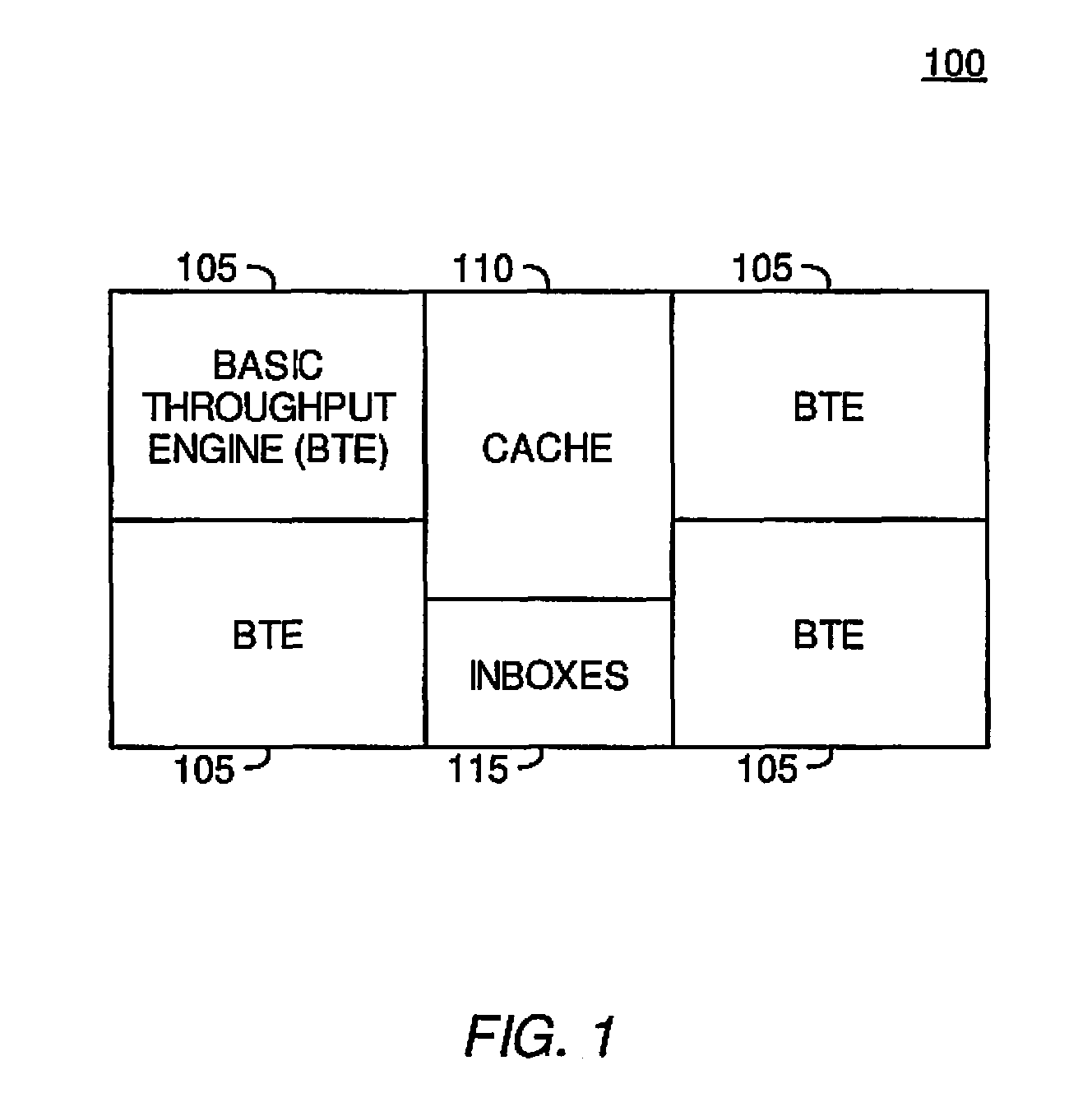
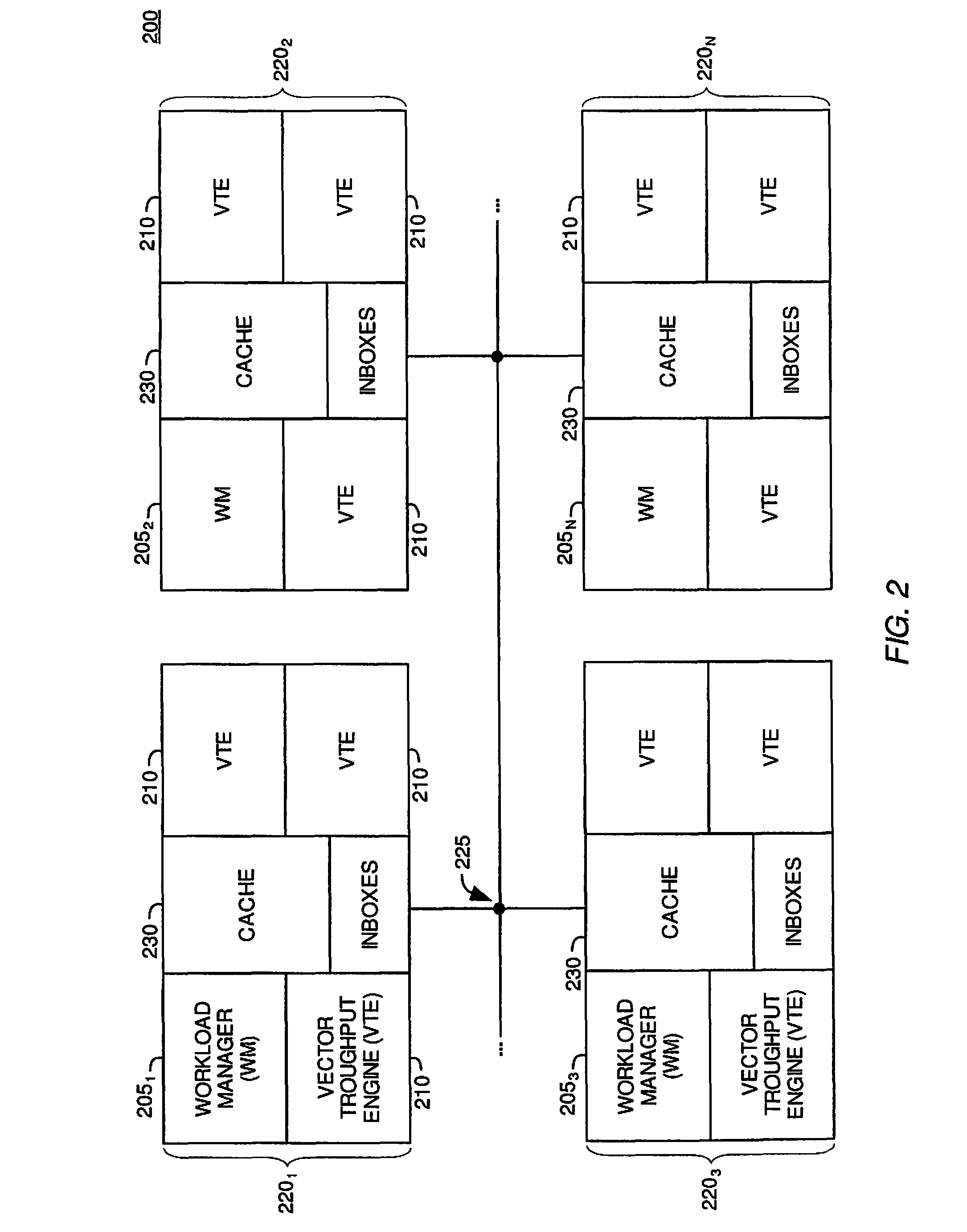
[0027]Embodiments of the invention provide systems and methods for distributing workload in a ray tracing image processing system. Evenly distributed workload in a ray tracing image processing system may result in faster and more efficient image processing.

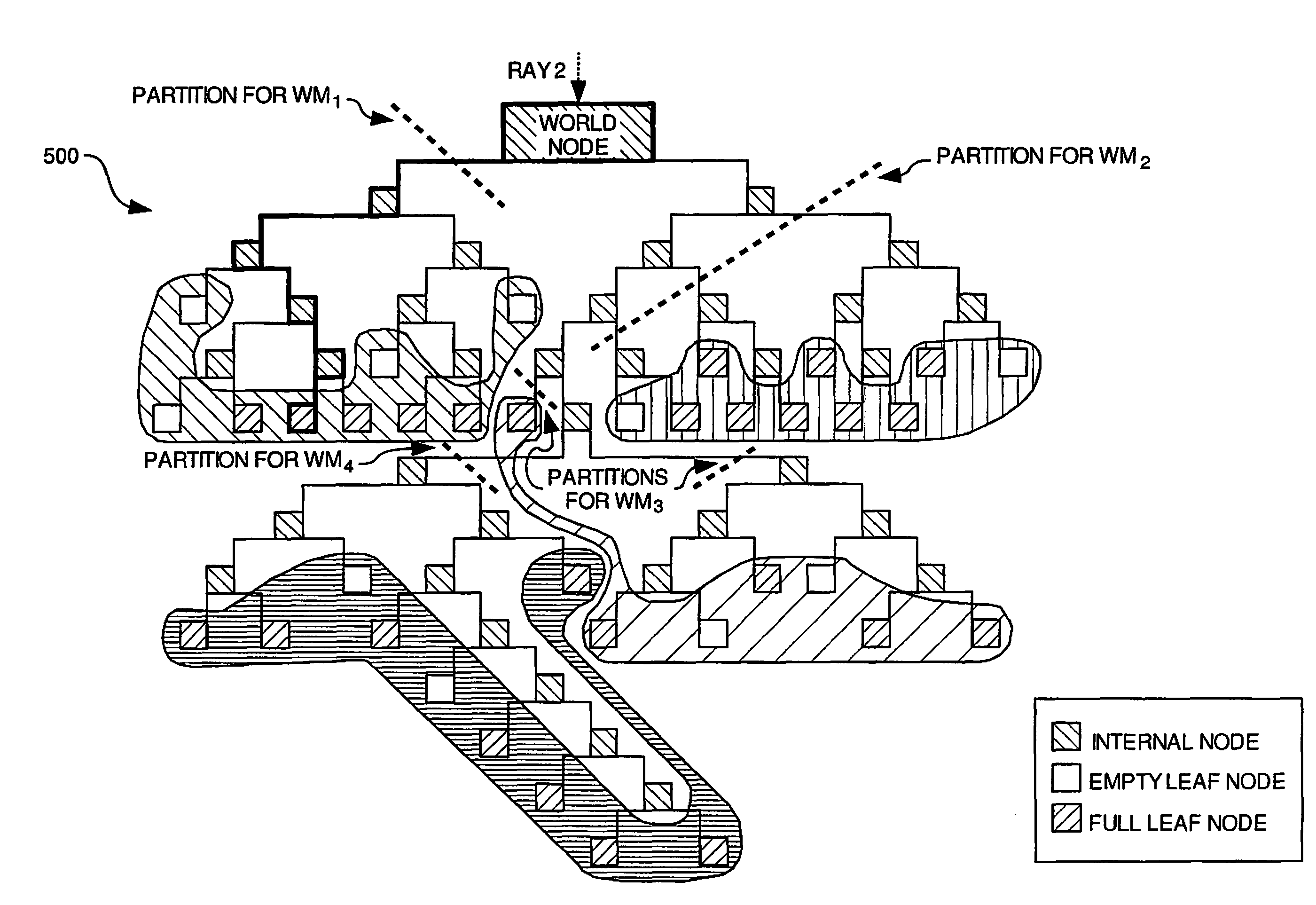
[0028]Some embodiments of the invention may evenly distribute workload by dividing a frame of pixels to be rendered into a plurality of regions, and assigning responsibility for each region to different processing elements. Each processing element may be responsible for performing a multitude of tasks for the pixels within their corresponding region, and these tasks may ultimately result in determining the color of those pixels. Furthermore, processing elements may be assigned responsibility to the regions of the frame based on the portions of a spatial index which they are responsible for traversing rays through.

[0029]Some embodiments of the invention may re-distribute workload amongst processing elements by re-dividing the frame...


PUM


Abstract

An image processing system may perform various tasks in an effort to evenly distribute workload amongst workload managers. According to one embodiment of the invention, the image processing system may divide a frame of pixels into different regions and assign responsibility for the regions to different workload managers in order to evenly distribute workload. The workload managers may be responsible for performing operations relating to determining or maintaining the color of the pixel within the region or regions which they are responsible. According to another embodiment of the invention, the image processing system may re-divide the frame into new regions based on relative workloads experienced by the processing elements to evenly distribute workload. Furthermore, according to another embodiment of the invention, the image processing system may re-partition a spatial index based on relative workloads experienced by the processing elements to evenly distribute workload amongst workload managers.

Description

BACKGROUND OF THE INVENTION[0001]1. Field of the Invention[0002]Embodiments of the invention generally relate to the field of computer processing.[0003]2. Description of the Related Art[0004]The process of rendering two-dimensional images from three-dimensional scenes is commonly referred to as image processing. As the modern computer industry evolves image processing evolves as well. One particular goal in the evolution of image processing is to make two-dimensional simulations or renditions of three-dimensional scenes as realistic as possible. One limitation of rendering realistic images is that modern monitors display images through the use of pixels.[0005]A pixel is the smallest area of space which can be illuminated on a monitor. Most modern computer monitors will use a combination of hundreds of thousands or millions of pixels to compose the entire display or rendered scene. The individual pixels are arranged in a grid pattern and collectively cover the entire viewing area of ...

Claims


Application Information

Patent Timeline
Patent Type & Authority Patents(United States)
IPC IPC(8): G06T15/50G06T15/40
CPCG06T15/06G06T2210/52
Inventor SHEARER, ROBERT A.
Owner ACTIVISION PUBLISHING
Why Eureka
Try Eureka