Reproducing signal measuring method, signal reproducing apparatus, and optical recording medium

a signal reproducing apparatus and signal technology, applied in the direction of digital signal error detection/correction, recording signal processing, instruments, etc., can solve the problems of interlayer crosstalk, pose a problem, inability to separate light rays from detectors, etc., to achieve small crosstalk, simple and quantitative measurement of interlayer crosstalk, favorable recording and reproducing characteristics

Inactive Publication Date: 2012-01-03
HITACHI CONSUMER ELECTRONICS CORP
View PDF11 Cites 0 Cited by
  • Summary
  • Abstract
  • Description
  • Claims
  • Application Information

AI Technical Summary

Benefits of technology

[0006]In view of the above-described problems, an object of the present invention is to provide a method for simply and quantitatively the influence of interlayer crosstalk caused in case that a multilayer optical recording medium has at least three recording layers, or provide a multilayer optical recording medium which makes it possible to simply and quantitatively the influence of interlayer crosstalk caused when the multilayer optical recording medium has at least three recording layers.
[0073]According to the present invention, it is possible to select and provide only a medium which is small in crosstalk and which has favorable recording and reproducing characteristics by evaluating the interlayer crosstalk.

Problems solved by technology

In the design of the multilayer optical recording medium, interlayer crosstalk caused by an unnecessary optical spot poses a problem as described above.
Thirdly, inability to separate light rays on the detector is also a factor which makes it difficult to quantitatively measure an interlayer crosstalk quantity caused by unnecessary light.
Heretofore, therefore, there has been no simple effective method for quantitatively measuring the interlayer crosstalk quantity caused by unnecessary light.

Method used


Image

  • Reproducing signal measuring method, signal reproducing apparatus, and optical recording medium
  • Reproducing signal measuring method, signal reproducing apparatus, and optical recording medium
  • Reproducing signal measuring method, signal reproducing apparatus, and optical recording medium

Examples


first embodiment

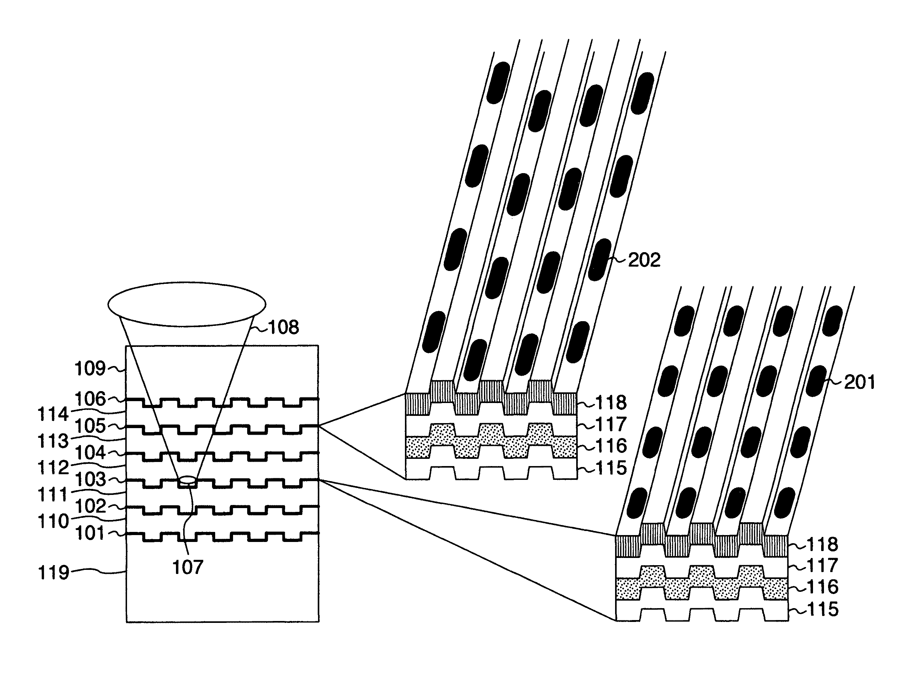
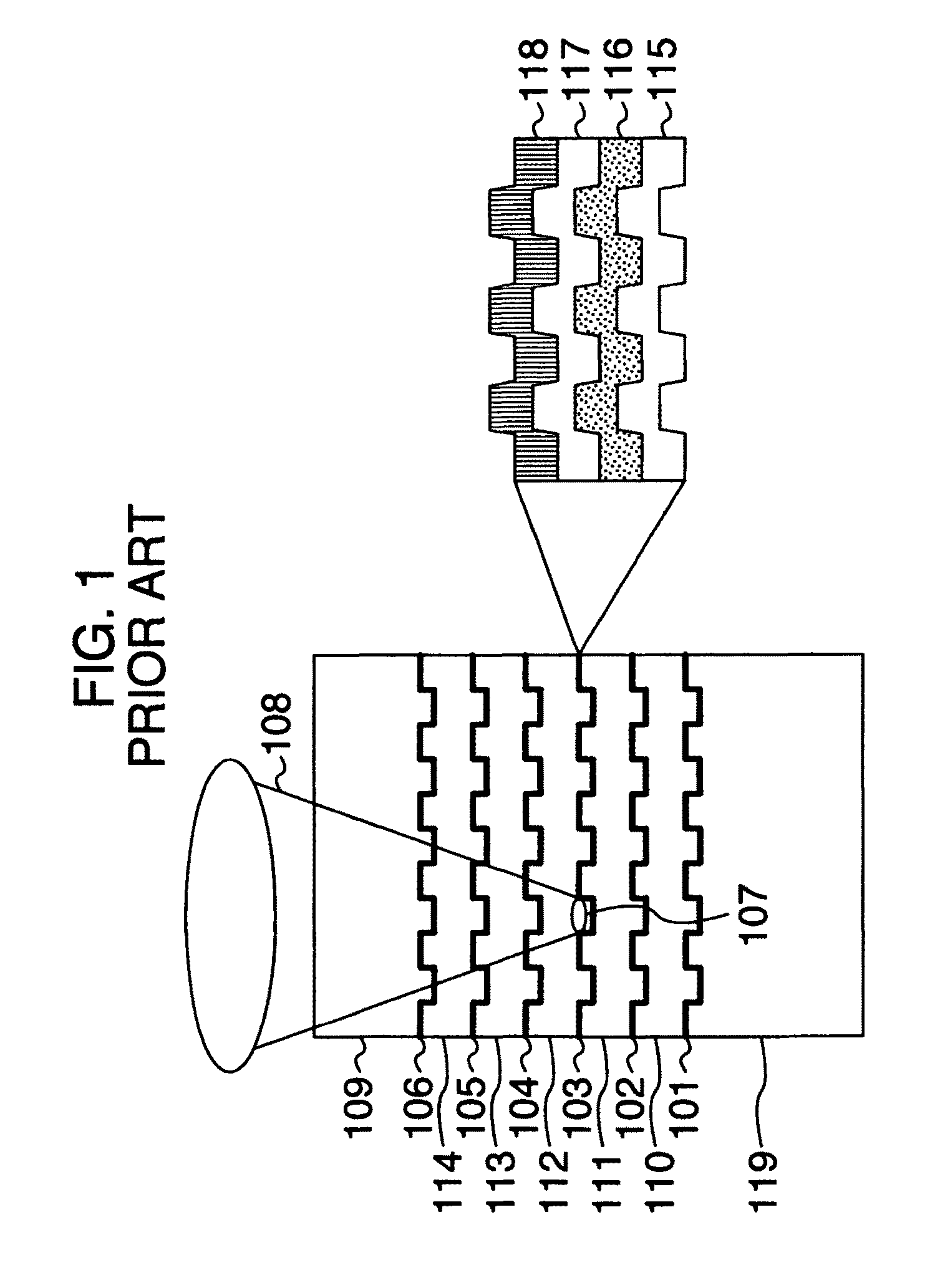
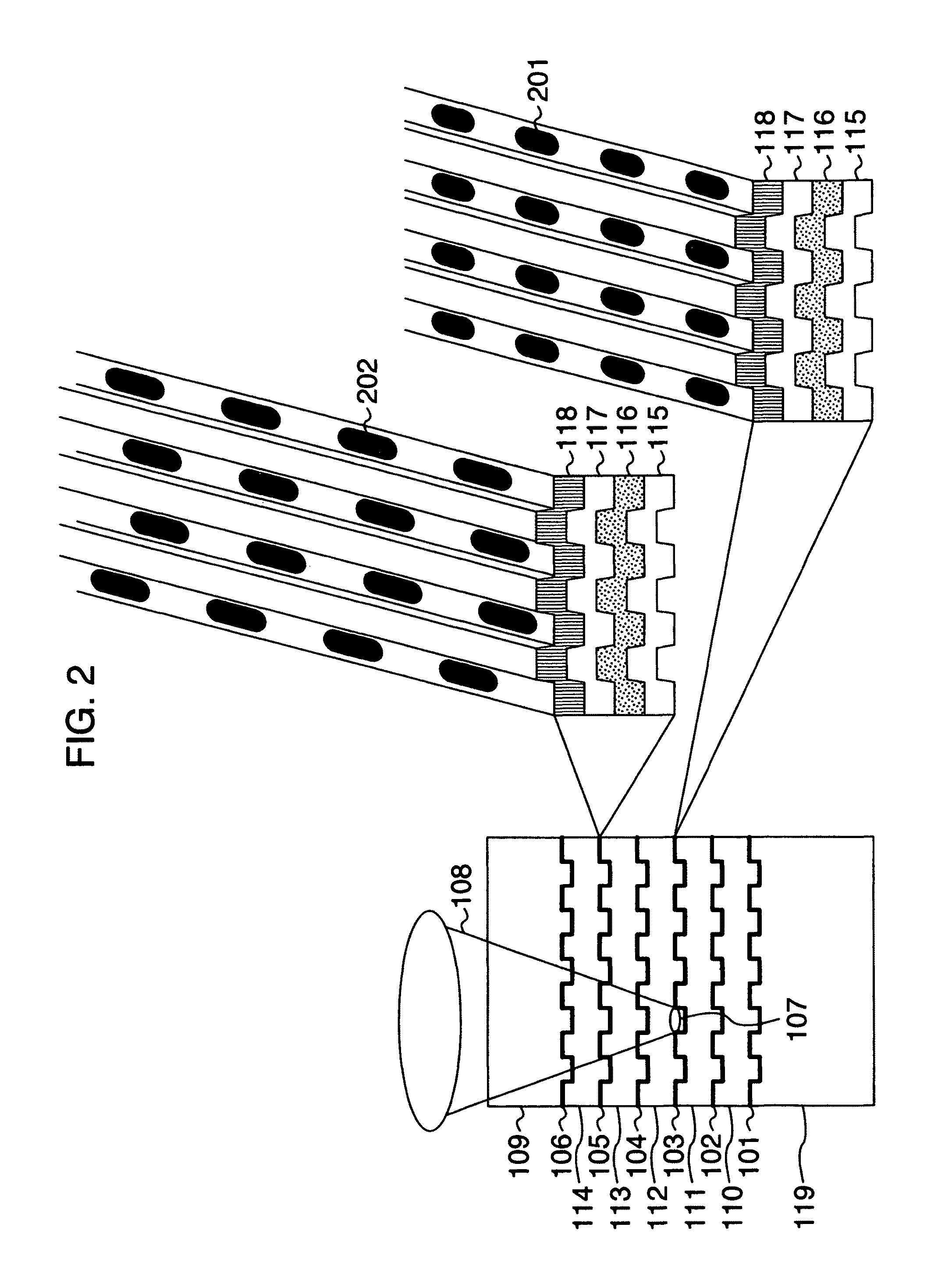
[0093]FIG. 2 schematically shows a sectional structure of a recording medium as one embodiment of the present invention. Here, a recording medium having six recording layers is mentioned as an example. The recording medium includes a substrate 119, a first recording layer 101, a second recording layer 102, a third recording layer 103, a fourth recording layer 104, a fifth recording layer 105 and a sixth recording layer 106 in the cited order beginning with the opposite side from the light incidence side used at the time of light irradiation. Each of layer spaces 110, 111, 112, 113 and 114 between recording layers is approximately 10 μm. A cover layer 109 of approximately 50 μm is formed over them. Converging rays 108 are applied from the incidence plane side, and an optical spot 107 is formed on a recording layer. Although each recording layer is typically formed of a reflection film 115, a protection film 116, a recording film 117 and a protection film 118, the recording layer may ...

second embodiment

[0111]In a second embodiment, a method for measuring interlayer crosstalk caused by an unnecessary optical spot serving as an embodiment of the present invention will be described. FIG. 11 shows a flow of the measurement. A recording type multilayer optical recording medium is set in a measurement apparatus, focusing is first conducted on an nth layer when counted from the opposite side from the light incidence side, and recording is conducted with a first frequency (step 1101, step is abbreviated to S in FIG. 11). Subsequently, focusing is conducted on an (n+2)nd layer, and recording is conducted by using a second frequency which is different from the first frequency (step 1102). In addition, reproducing is conducted on the nth layer (step 1103). A signal of the first frequency and a signal of the second frequency are separated from the reproducing signal (step 1104). Finally, signal amplitude of the first frequency and a maximum value of signal amplitude of the second frequency ar...

third embodiment

[0118]Interlayer crosstalk caused by an unnecessary optical spot in a recording medium having at least five recording layers will now be described in the same way as the first embodiment of the present invention with reference to FIG. 15. Supposing that the target layer of recording and reproducing is the nth layer, incidence light 108 formed of converging rays is applied so as to form an optical spot 107 on the nth layer as shown in FIG. 15. At this time, light reflected by the (n+2)nd layer which is located on this side of the target layer by two layers becomes unnecessary light 402 and arrives at the back of the (n+4)th layer. The unnecessary light 402 reflected by the back of the (n+4)th layer is reflected by the (n+2)nd layer again, and follows nearly the same path as that of light reflected by the nth layer and returns toward the optical pickup, resulting in large interlayer crosstalk. In this way, unnecessary light is formed on a layer not only when there are two layers but a...


PUM

PropertyMeasurementUnit
thicknessaaaaaaaaaa
thicknessaaaaaaaaaa
thicknessaaaaaaaaaa

Abstract

Regarding a signal recorded with a first frequency in a recording area on a specific first recording layer and a signal recorded with a second frequency different from the first frequency in a recording area on a second recording layer which might cause interlayer crosstalk in relation to the first recording layer, a reproducing signal measurement method for a multilayer optical recording medium having at least three recording layers includes reproducing the signal recorded in the recording area on the first recording layer, separating signals recorded respectively with the first and second frequencies, discriminating signal amplitude of the first frequency and a maximum value in signal amplitude of the second frequency, and calculating a signal amplitude ratio between them to measure interlayer crosstalk contained in the signal reproduced from the recording area on the first recording layer. Thus, the interlayer crosstalk quantity caused by unnecessary light can be measured quantitatively.

Description

INCORPORATION BY REFERENCE[0001]The present application claims priority from Japanese application JP 2007-206045 filed on Aug. 8, 2007, the content of which is hereby incorporated by reference into this application.BACKGROUND OF THE INVENTION[0002]The present invention relates to a reproducing signal measuring method for optical recording medium with due regard to interlayer crosstalk of the optical recording medium having a plurality of recording layers, and a signal reproducing apparatus and an optical recording medium having a plurality of recording layers which realize the reproducing signal measuring method.[0003]FIG. 1 shows a sectional structure of a conventionally known multilayer optical disk among optical recording media. A principle for selectively recording and reproducing information of each recording layer is schematically shown in FIG. 1. In the conventional art, a recording medium includes a total of six layers having information recorded thereon (hereafter referred ...

Claims


Application Information

Patent Timeline
Patent Type & Authority Patents(United States)
IPC IPC(8): G11B7/00G11B7/24038G11B7/24097
CPCG11B7/005G11B7/24038G11B20/22G11B20/1217G11B2007/0013G11B2020/1298G11B2220/235G11B2220/2537
Inventor HIROTSUNE, AKEMIUSHIYAMA, JUNKOMINEMURA, HIROYUKIKUROKAWA, TAKAHIROMIYAMOTO, HARUKAZU
Owner HITACHI CONSUMER ELECTRONICS CORP
Why Eureka
Try Eureka