Magnetooptic recording medium and its manufacturing method

a technology of magnetic recording medium and manufacturing method, which is applied in mechanical recording, light beam reproducing, instruments, etc., can solve the problems of sudden decrease in the amplitude of the signal to be read out, and achieve the effect of improving jitter characteristics and high recording density

Inactive Publication Date: 2007-02-06
SONY CORP
View PDF15 Cites 3 Cited by
  • Summary
  • Abstract
  • Description
  • Claims
  • Application Information

AI Technical Summary

Benefits of technology

[0022]Typically, the invention is applied to a reproducing method called RAD (Rear Aperture Detection) in which the signal is detected in a rear high temperature portion in the reproducing light spot. Specifically speaking, the invention is applied to a magnetooptic recording medium using a double mask type RAD system in which masks are formed in forward and backward portions in the progressing direction of the spot called D-RAD. According to the RAD system, since a high temperature area having a width smaller than a width of spot in the spot becomes a detection area of the recording mark, as compared with a FAD system in which a low temperature area C of the spot is used as a detection area, a width in the track direction of the detection area is narrower, a crosstalk from the adjacent track is smaller, and a ratio at which the invention contributes to the realization of a high recording density is larger.
[0023]According to the invention constructed as mentioned above, in the magnetooptic recording medium provided with the multilayer magnetic film having the second magnetic layer having inplane magnetic anisotropy at room temperature, a pressure of the second magnetic layer upon film creation is higher than 0.6 Pa and is equal to or lower than 3.0 Pa and saturation magnetization of the second magnetic layer at room temperature is larger than 8.80×10⁻² Wb / m2 and is less than 1.76×10⁻¹ Wb / m2. Thus, jitter characteristics can be improved while a recording power margin and a reproducing power margin of the laser beam are assured in a sufficiently wide range.

Problems solved by technology

However, to realize microminiaturization of the recording mark as mentioned above, a sudden decrease in amplitude of the signal to be read out becomes a problem.

Method used


Image

  • Magnetooptic recording medium and its manufacturing method
  • Magnetooptic recording medium and its manufacturing method
  • Magnetooptic recording medium and its manufacturing method

Examples


Embodiment Construction

[0038]An embodiment of the invention will be described hereinbelow with reference to the drawings. In all of the following diagrams of the embodiment, the same or corresponding portions are designated by the same reference numerals.

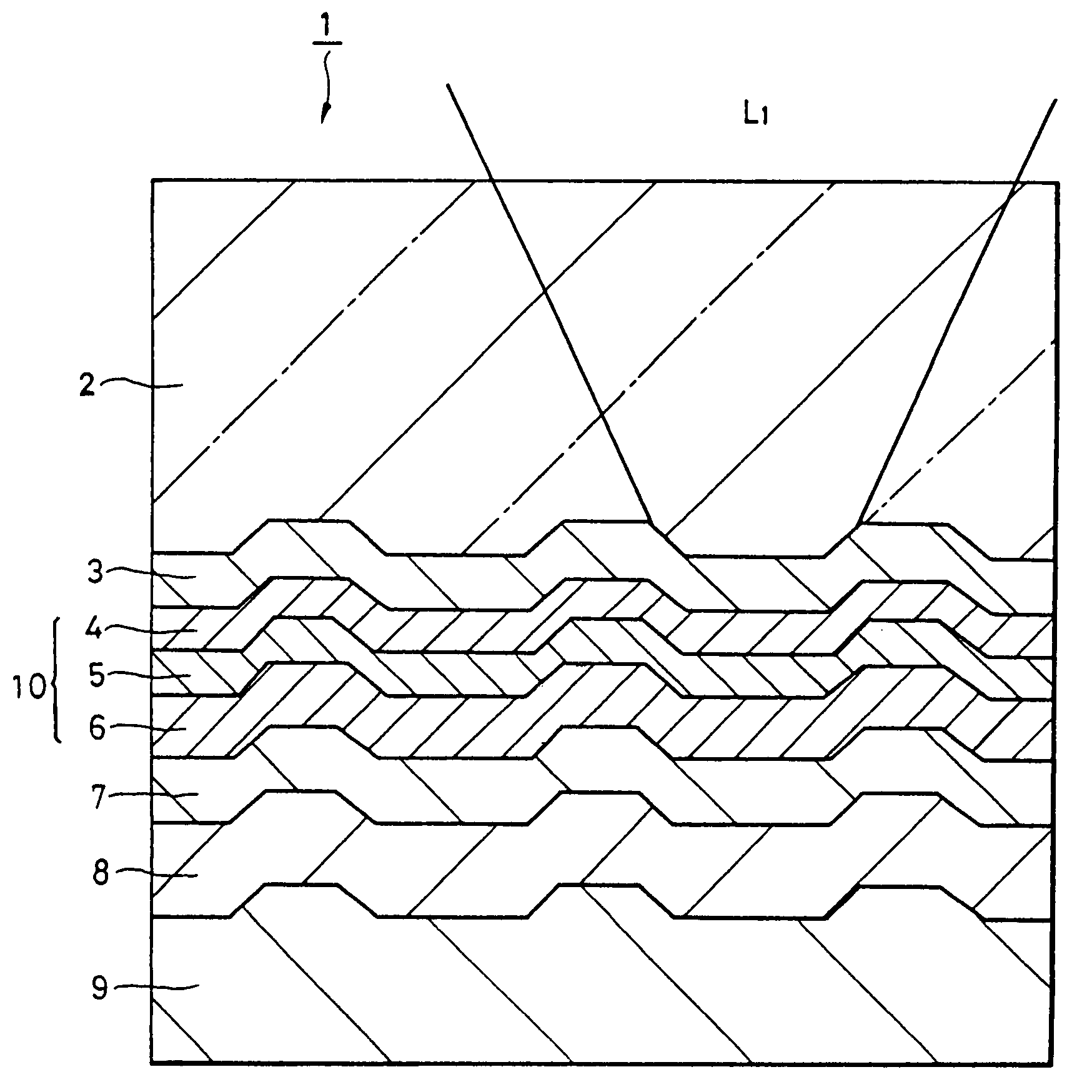
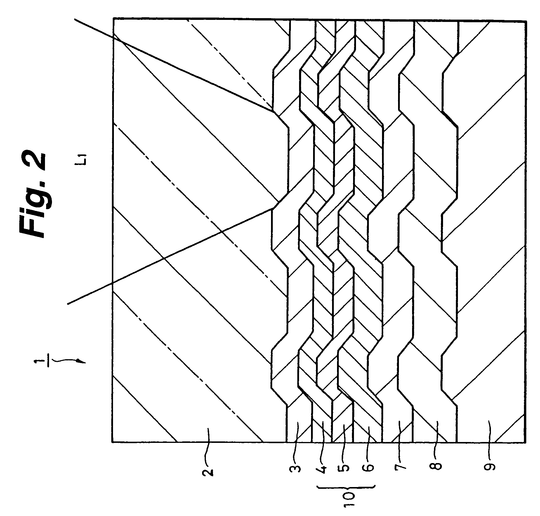
[0039]First, a magnetooptic disk according to the embodiment of the invention will be described. FIG. 2 shows the magnetooptic disk according to the first embodiment.

[0040]As shown in FIG. 2, a magnetooptic disk 1 according to the embodiment is constructed by sequentially laminating a first dielectric layer 3, a first magnetic layer 4, a second magnetic layer 5, a third magnetic layer 6, a second dielectric layer 7, a reflective layer 8, and a protective layer 9 onto one principal plane of a disk substrate 2.

[0041]The disk substrate 2 is made by molding a resin material into a disk shape by, for example, an injection molding method. For example, glass 2P or the like or a synthetic resin material such as polycarbonate (PC) or the like is used as a resin ma...


PUM

PropertyMeasurementUnit
thicknessaaaaaaaaaa
thicknessaaaaaaaaaa
atmospheric pressureaaaaaaaaaa

Abstract

A first dielectric layer 3, a multilayer magnetic film 10 in which a first magnetic layer 4 having perpendicular magnetic anisotropy at room temperature, a second magnetic layer 5 having inplane magnetic anisotropy at room temperature, and a third magnetic layer 6 having perpendicular magnetic anisotropy at room temperature are sequentially laminated, a second dielectric layer 7, a reflective layer 8, and a protective layer 9 are sequentially laminated onto one principal plane of a disk substrate 2 on which a land and a groove exist, thereby forming a magnetooptic disk 1. Saturation magnetization of the second magnetic layer 5 is set to a range from 8.80×10⁻² to 1.76×10⁻¹ Wb / m2. A gas pressure upon film creation of the second magnetic layer is set to a range from 0.6 to 3.0 Pa. A content ratio of Co in the third magnetic layer 6 is set to a range from 15 to 17 atom %.

Description

BACKGROUND OF THE INVENTION[0001]The invention relates to a magnetooptic recording medium and its manufacturing method and, more particularly, to a magnetooptic recording medium and its manufacturing method which are suitable to be applied to a magnetooptic disk, a magnetooptic tape, and a magnetooptic card in which Magnetically Induced Super Resolution reproduction can be performed.[0002]Hitherto, in association with the realization of a high density of recording marks in a magnetooptic disk, a further increase in recording capacity is progressing. To increase the recording capacity as mentioned above, a method of realizing the high density by reducing a length of recording mark, narrowing a track pitch, and microminiaturizing a recording pit is used.[0003]As means which is effective in realizing the high density, a Magnetically Induced Super Resolution technique (MSR) by which the recording mark smaller than a spot diameter of a laser beam can be reproduced has been proposed (for ...

Claims


Application Information

Patent Timeline
Patent Type & Authority Patents(United States)
IPC IPC(8): G11B11/00B32B3/02G11B7/00G11B11/105
CPCG11B11/10586G11B7/00G11B11/105
Inventor WADA, YUTAKANAKAYAMA, HIROSHI
Owner SONY CORP
Why Eureka
Try Eureka