Movable injectors in rotating disc gas reactors

a technology of rotating disc and injector, which is applied in the direction of vacuum evaporation coating, chemical vapor deposition coating, coating, etc., can solve the problems of profoundly affecting the performance of the resulting devi

Inactive Publication Date: 2012-01-10
VEECO INSTR
View PDF37 Cites 60 Cited by
  • Summary
  • Abstract
  • Description
  • Claims
  • Application Information

AI Technical Summary

Problems solved by technology

Small differences in the properties of each layer can profoundly affect the performance of the resulting device.

Method used


Image

  • Movable injectors in rotating disc gas reactors
  • Movable injectors in rotating disc gas reactors
  • Movable injectors in rotating disc gas reactors

Examples


Embodiment Construction

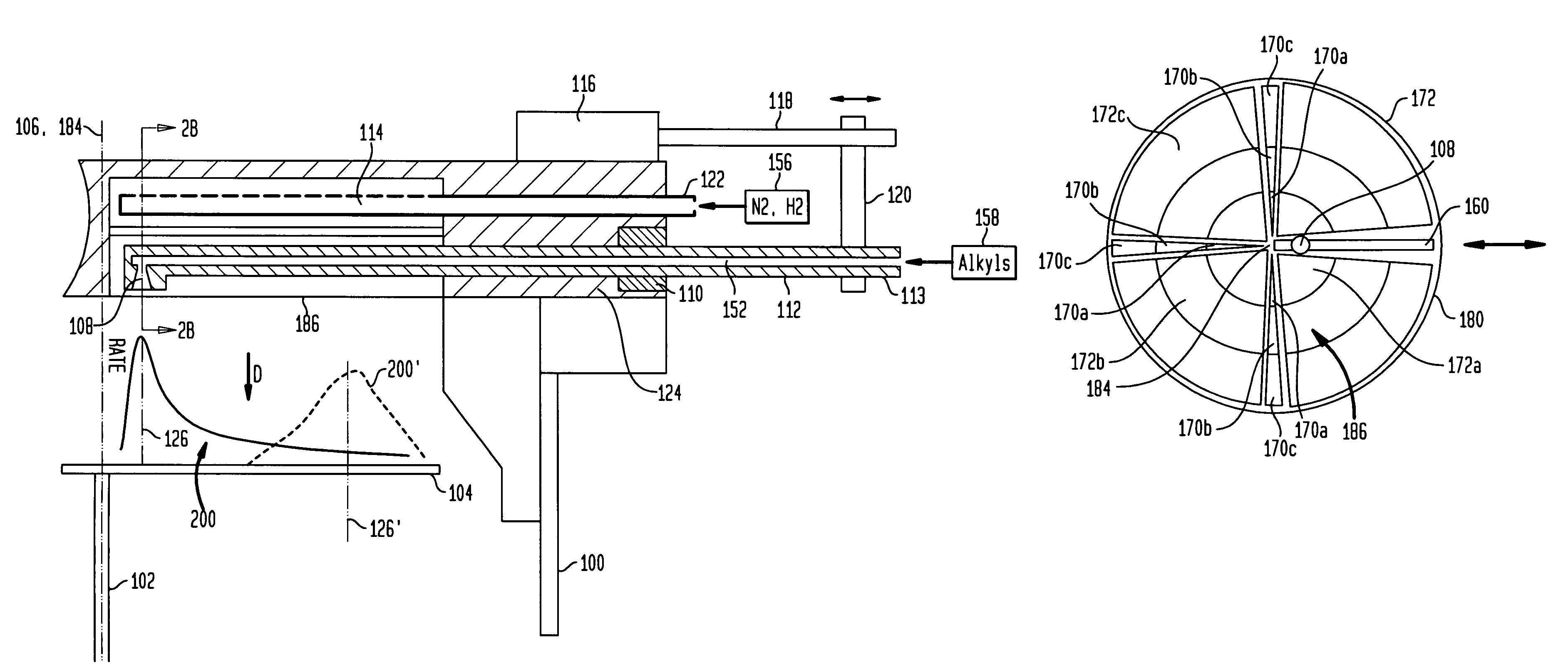
[0031]While the present invention is particularly well suited for use in MOCVD (metalorganic chemical vapor deposition) rotating disk reactors and is so described herein, it is equally well suited for other rotating disk gas treatment systems. MOCVD is a method of epitaxial growth of materials, especially semiconductors from the surface reaction of metalorganics and metal hydrides containing the required chemical elements. For example, indium phosphide can be grown by introducing trimethylindium (CH3)3In and phosphine PH3. Alternate names for this deposition process include metalorganic vapor phase epitaxy (MOVPE), organometallic vapor phase epitaxy (OMVPE), and organometallic chemical vapor deposition (OMCVD).

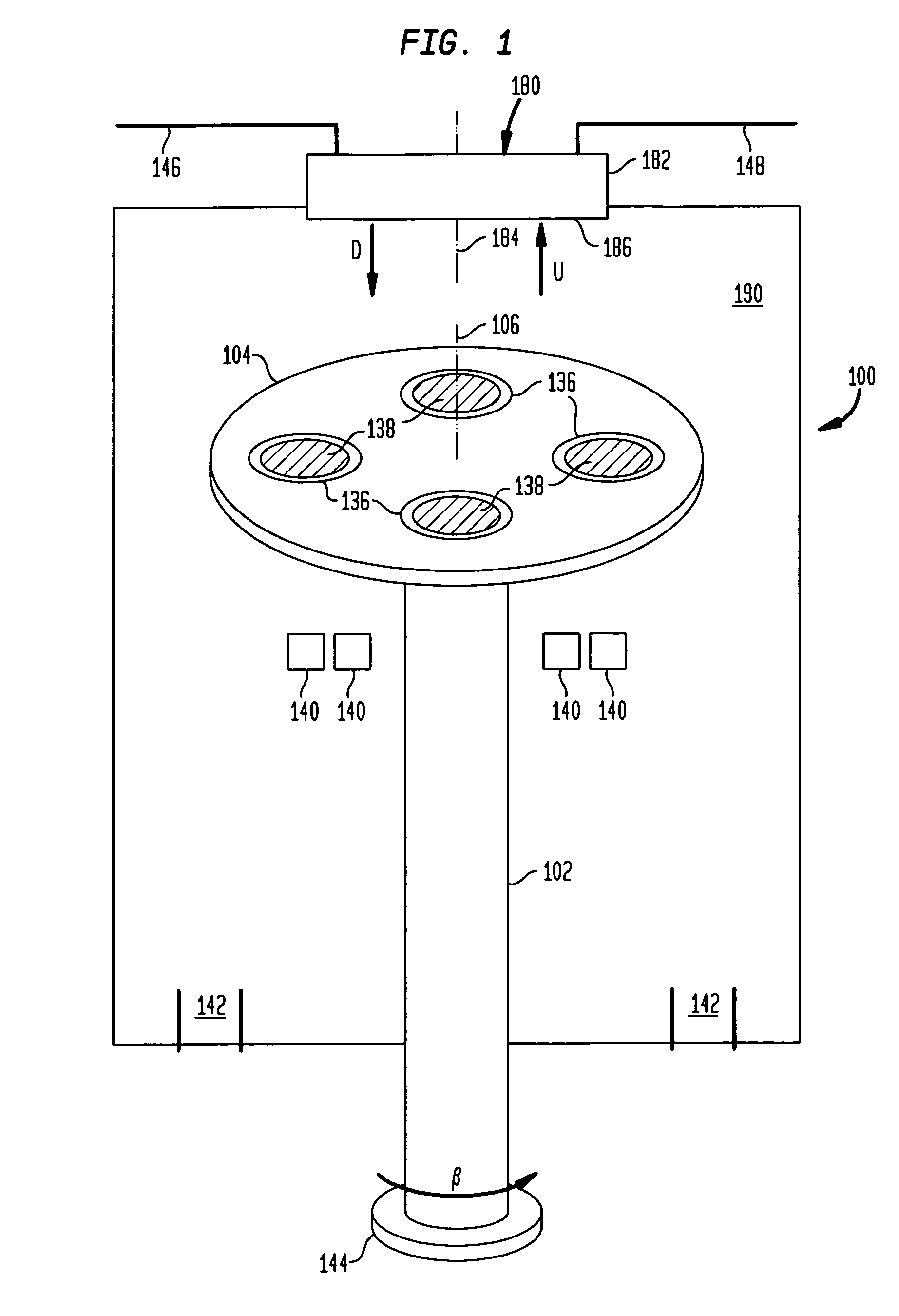
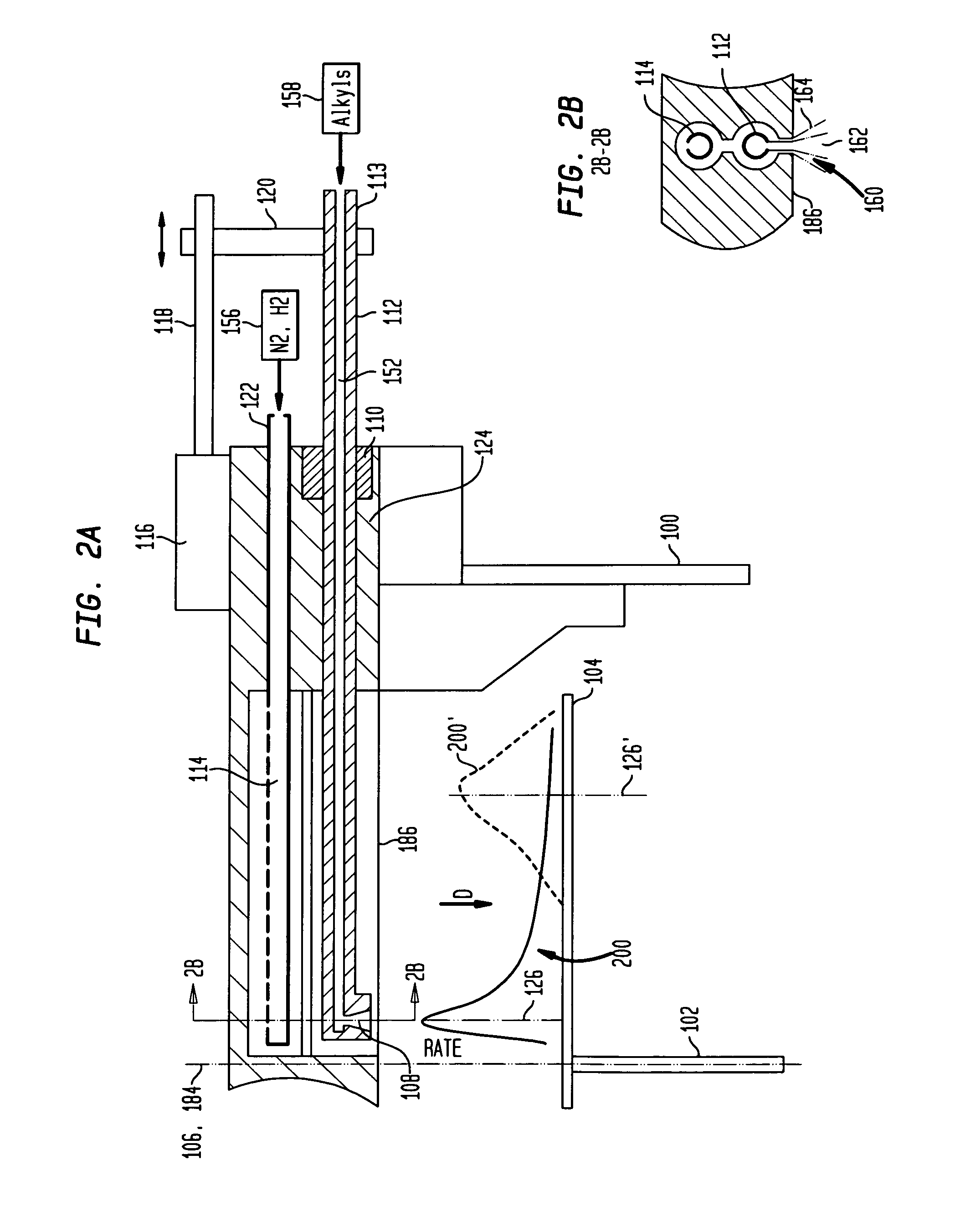
[0032]The rotating disk gas treatment reactor is a chamber which can withstand high temperatures and has an interior which does not react with the chemicals being used. The chamber contains a rotating susceptor (substrate carrier), gas injection modules, and temperature contro...


PUM

PropertyMeasurementUnit
temperatureaaaaaaaaaa
speedsaaaaaaaaaa
speedsaaaaaaaaaa

Abstract

A system and method for uniform deposition of material layers on wafers in a rotating disk chemical vapor deposition reaction system is provided, wherein one or more substrates are rotated on a carrier about an axis while maintaining surfaces of the one or more substrates substantially perpendicular to the axis of rotation and facing in an upstream direction along the axis of rotation. During rotating a first gas is discharged in the downstream direction towards the one or more substrates from a first set of gas inlets. A second gas is discharged in the downstream direction towards the one or more substrates from at least one movable gas injector, and the at least one movable gas inlet is moved with a component of motion in a radial direction towards or away from the axis of rotation.

Description

BACKGROUND OF THE INVENTION[0001]Gas treatment apparatus such as chemical vapor deposition systems are used to treat substrates such as semiconductor wafers. One form of apparatus commonly used is a rotating disk reactor. Such a reactor includes a chamber and a disk-like substrate carrier mounted within the chambers. Substrates such as wafers are disposed on the carrier, and the carrier is rotated about its axis. A component referred to as a gas distribution injector or “injector head” is mounted in fixed position on the chamber. The gas injector head typically includes numerous gas inlets. One or more reactive gases are injected into the chamber through these inlets and flow generally in a downstream direction toward the substrate carrier, and outwardly across the rotating substrate carrier and the surfaces of the substrates disposed on the carrier. Carrier gases may be injected along with the reactive gases.[0002]As the gases pass across the surfaces of the wafers, they react and ...

Claims


Application Information

Patent Timeline
Patent Type & Authority Patents(United States)
IPC IPC(8): C23C16/00C23C16/455H01L21/306
CPCC23C16/45589C23C16/52H01L21/02365
Inventor SFERLAZZO, PIEROGURARY, ALEXANDER I.ARMOUR, ERIC A.QUINN, WILLIAM E.TING, STEVE
Owner VEECO INSTR
Why Eureka
Try Eureka