Intraocular gas injector

a gas injector and gas technology, applied in the field of intraocular gas injectors, can solve the problems of increasing increasing the risk of errors, and achieving the effect of reducing the likelihood of errors, reducing the time necessary to fill the syringe, and simplifying the procedur

Active Publication Date: 2015-03-24
ALCON INC
View PDF7 Cites 11 Cited by
  • Summary
  • Abstract
  • Description
  • Claims
  • Application Information

AI Technical Summary

Benefits of technology

[0011]An aspect of at least one of the inventions disclosed herein includes the realization that an intraocular gas injector design can allow a surgeon or a nurse to prepare a gas mixture with a selected concentration level using a simplified procedure. For example, in some known intraocular gas injector devices and procedures, such as conventional syringes, multiple parties can be required to fill the syringe to achieve a desired concentration with one person repeatedly filling and discharging the syringe and another person controlling the flow of a gas contained in an external tank. Additionally, each person must coordinate their actions and perform a multitude of complex steps. This increases the potential for errors in the filling process which could result in an improper concentration being achieved in the syringe prior to injection into a patient. Furthermore, this can increase the time necessary to fill the syringe as the two parties must coordinate their activities and perform multiple steps. The potential for error can be particularly dangerous in certain medical fields, such as ophthalmology, where injection of an improper concentration can result in blindness. Thus, an intraocular gas injector that can be operated by a single person can help reduce the likelihood of error.
[0012]Another aspect of at least one of the inventions disclosed herein includes the realization that an intraocular gas injector design can allow for multiple selectable concentration levels thereby allowing one device to be used for different applications and thus potentially further reducing manufacturing costs and waste. For example, some conventional devices can only allow for a preset concentration level to be achieved within the device thereby necessitating the manufacturing and storage of multiple devices having different preset concentration level. This increases both the costs of manufacturing and the cost to a surgeon who needs to purchase multiples of each device to accommodate for different surgical needs. Under such circumstances, some devices can expire thereby requiring the manufacturer or surgeon to dispose of such devices without ever having been used. As such, an intraocular gas injector that allows for multiple concentration levels can serve as a one-size fits all for a surgeon thereby reducing waste.
[0013]Another aspect of at least one of the inventions disclosed herein includes the realization that an intraocular gas injector design can allow for automated operation during at least some phases of operation thereby reducing the potential for errors in achieving a proper concentration level. For example, in some known intraocular gas injector devices and procedures, such as conventional syringes, a nurse or other operating room personnel must physically measure the amount of gas contained within a syringe during a first phase of operation. In a situation where a minute change in volume can result in a significant change in concentration, a minor error in this physical measurement can result in an improper concentration being achieved in the syringe after all phases of operation have been completed. Therefore, an intraocular gas injector that automatically measures the volume in the first phase and / or any other phase can reduce the likelihood of an improper concentration being achieved in the injector.

Problems solved by technology

Additionally, each person must coordinate their actions and perform a multitude of complex steps.
This increases the potential for errors in the filling process which could result in an improper concentration being achieved in the syringe prior to injection into a patient.
Furthermore, this can increase the time necessary to fill the syringe as the two parties must coordinate their activities and perform multiple steps.
The potential for error can be particularly dangerous in certain medical fields, such as ophthalmology, where injection of an improper concentration can result in blindness.
For example, some conventional devices can only allow for a preset concentration level to be achieved within the device thereby necessitating the manufacturing and storage of multiple devices having different preset concentration level.
This increases both the costs of manufacturing and the cost to a surgeon who needs to purchase multiples of each device to accommodate for different surgical needs.
Under such circumstances, some devices can expire thereby requiring the manufacturer or surgeon to dispose of such devices without ever having been used.
In a situation where a minute change in volume can result in a significant change in concentration, a minor error in this physical measurement can result in an improper concentration being achieved in the syringe after all phases of operation have been completed.

Method used


Image

  • Intraocular gas injector
  • Intraocular gas injector
  • Intraocular gas injector

Examples


embodiment

of Pressurized Chamber

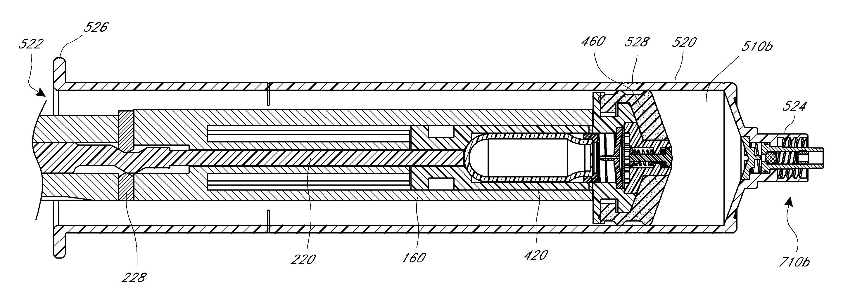
[0145]With reference to FIG. 24, an embodiment of a pressurized chamber is shown along with components of an activation system. As illustrated, the pressurized chamber can have a two-part housing with a first housing member 1020 and a second housing member 1022 which are translatable with respect to each other. As shown in the illustrated embodiment, the two members 1020, 1022 can have a generally cylindrical shape such that some or all portions of the two members 1020, 1022 can be received within a channel 868 of the plunger body 860. In some embodiments, the two members 1020, 1022 can be detached from one another to allow free translation of the two members 1020, 1022. In other embodiments, the two-part housing can be attached while still allowing translation of the members 1020, 1022 with respect to each other. Such attachment can be used to increase the stability of the two members 1020, 1022.

[0146]As shown in the illustrated embodiment and similar to other...


PUM

PropertyMeasurementUnit
total volumeaaaaaaaaaa
lengthaaaaaaaaaa
lengthaaaaaaaaaa

Abstract

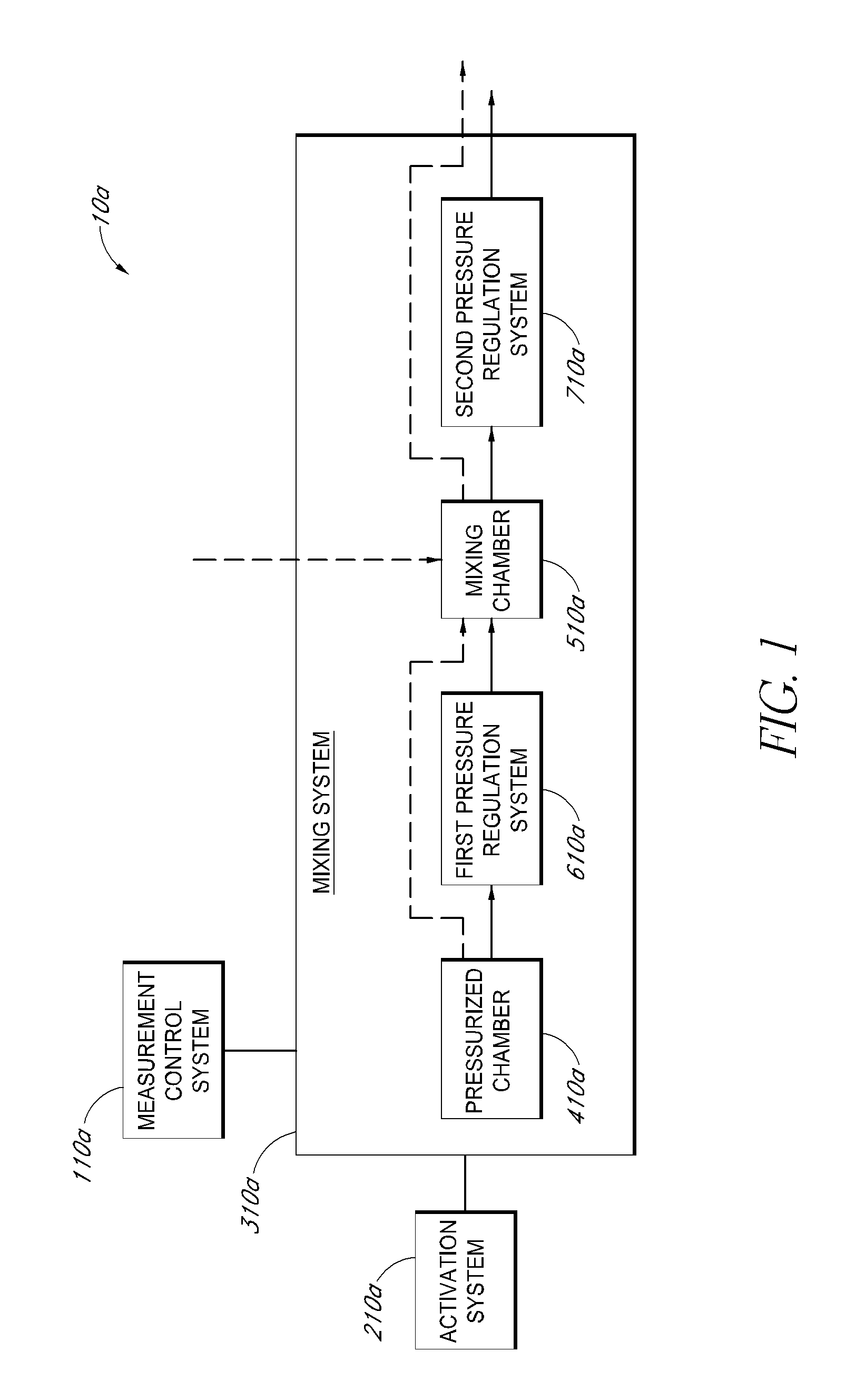
A gas mixture apparatus includes a measurement control system, an activation system, a pressurized chamber with one or more gases, and a mixing chamber. The apparatus can also include additional pressure regulation control systems. The gas mixture apparatus can be used to introduce and automatically perform the steps to achieve a desired concentration of the one or more gases contained in the pressurized chamber. The gas mixture apparatus can include the pressurized chamber within the apparatus itself such that no external devices are necessary for introducing the one or more gases into the mixing chamber.

Description

RELATED APPLICATIONS[0001]The present application claims priority to U.S. Provisional Application No. 61 / 658,765 filed Jun. 12, 2012, entitled INTRAOCULAR GAS INJECTOR and U.S. Provisional Application No. 61 / 799,840 filed Mar. 15, 2013, entitled INTRAOCULAR GAS INJECTOR, the entire contents of both of which are hereby expressly incorporated by reference.TECHNICAL FIELD[0002]The inventions disclosed herein generally relate to devices and methods for injecting gases into an eye of an animal.BACKGROUND OF THE INVENTIONS[0003]Surgical procedures can require gases or other fluids to be injected into a target area for treatment of certain injuries, disorders and diseases. In the treatment of eye conditions such as macular holes, retinal tears and detachments, part of the surgical procedure can include the injection of gases or other fluids into the eye.[0004]For example, retinal detachment is an eye disorder involving the separation of the retina from the Retinal Pigment Epithelium (RPE),...

Claims


Application Information

Patent Timeline
Patent Type & Authority Patents(United States)
IPC IPC(8): A61F9/007A61M5/31A61M5/315B01F23/10
CPCA61F9/007A61F9/00727A61M5/3145A61M5/31596A61M2005/3128A61M2202/02A61M2210/0612A61M5/31553A61M5/3156A61M5/3158
Inventor AULD, JACK R.MCCOLLAM, CHRISTOPHER L.
Owner ALCON INC
Why Eureka
Try Eureka