

Gas injector and apparatus including the same
a technology of gas injector and gas injector, which is applied in the direction of instruments, non-linear optics, coatings, etc., can solve the problems of increased fabrication cost of gas injector, non-uniform gas distribution, and shortened production period of gas injector, so as to reduce fabrication cost and shorten production period
- Summary
- Abstract
- Description
- Claims
- Application Information
AI Technical Summary
Benefits of technology
Problems solved by technology
Method used
Image

Examples
first embodiment
[0037]FIGS. 4 and 5 are a schematic cross-sectional view and a schematic perspective view, respectively, showing a gas injector of a plasma apparatus according to the present invention.
[0038]In FIGS. 4 and 5, a gas injector 100 includes a plate 110 and a plurality of nozzle modules 160. Even though not shown in FIGS. 4 and 5, the plate functions as a lower plate in a plasma apparatus including an upper plate functioning as a plasma electrode for a radio frequency (RF) power. The plate 110 includes a plurality of first injection holes 112 and a plurality of openings 116 corresponding to the plurality of first injection holes 112. Each opening 116 is formed on the corresponding first injection hole 112, and each nozzle module 160 can be attached to and detached from the plate 110. Accordingly, each nozzle module 160 is detachable with respect to the plate 110. Each opening 116 is formed in the plate 110 as a concave portion to have a diameter greater than a diameter of each first inje...
second embodiment
[0043]FIGS. 6 and 7 are a schematic cross-sectional view and a schematic perspective view, respectively, showing a gas injector of a plasma apparatus according to the present invention.
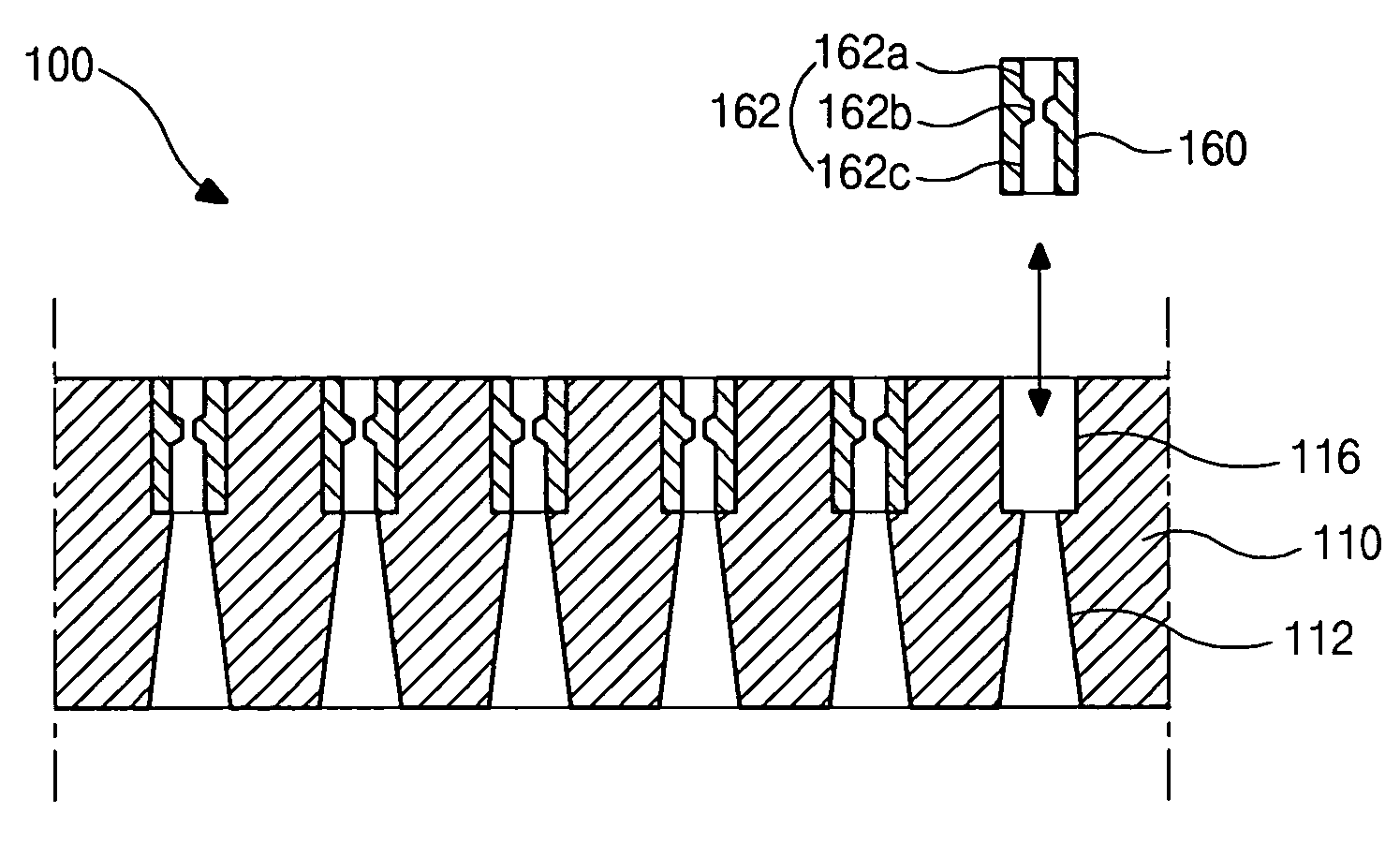
[0044]In FIGS. 6 and 7, a gas injector 100 includes a plate 110 and a plurality of nozzle modules 160. Each first injection hole 112 of the plate 110 may have a tapering hollow shape such that a diameter gradually increases with a distance from a top portion, and a second injection hole 162 of the nozzle module 160 may have a sandglass hollow shape including a gas inlet portion 162a, a nozzle portion 162b and a diffusing portion 162c. As a result, a thickness of the nozzle module 160 of the second embodiment may increase as compared with the nozzle module 160 of the first embodiment.
third embodiment
[0045]FIGS. 8 and 9 are a schematic cross-sectional view and a schematic perspective view, respectively, showing a gas injector of a plasma apparatus according to the present invention.
[0046]In FIGS. 8 and 9, a gas injector 100 includes a plate 110 and a plurality of nozzle modules 160. The plate 110 includes a plurality of first injection holes 112 and a plurality of openings 116. The nozzle module 160 includes a plurality of second injection holes 162 and can be inserted into the opening 116. Here, a single opening 116 corresponds to a plurality of first injection holes 112 instead of a single first injection hole. For example, when the nozzle module 160 is inserted into the opening 116 corresponding to nine first injection holes 112, the nozzle module 160 may include nine second injection holes 162 each corresponding to the single first injection hole 112. As a result, a single opening 116 may correspond to nine first injection holes 112 and nine second injection holes 162. In an...
PUM
| Property | Measurement | Unit |
|---|---|---|
| diameter | aaaaa | aaaaa |
| thickness | aaaaa | aaaaa |
| thickness | aaaaa | aaaaa |
Abstract
Description
Claims
Application Information