Device for influencing a light beam in particular for stage illumination

a technology for stage illumination and light beams, which is applied in the field of devices for influencing light beams, can solve the problems of correspondingly large space occupation of primitive elements and substantial decrease of primitive elements, and achieve the effects of reducing the size of primitive elements, improving appearance, and improving mounting

Active Publication Date: 2012-01-17
GLP GERMAN LIGHT PRODS
View PDF5 Cites 14 Cited by
  • Summary
  • Abstract
  • Description
  • Claims
  • Application Information

AI Technical Summary

Benefits of technology

[0007]At least the basic parts of the control electronics are housed in the arm or head and at least one of the drives is housed in the rotatable arm, which leads to a substantial decrease of the size of the primitive element. This does not only lead to a better appearance but, in particular, also has advantages regarding the placement in stage settings. On the one hand, due to the smaller primitive element a better mounting to the crossbars is possible which are usually provided for mounting illumination elements. In particular, however, the primitive element covers existing sets as little as possible, so that the device may be used without problems and in many ways. Thus, it is not needed any more to hide the primitive element in sets by coloring the same using a corresponding set color which varies from set to set. Constant expensive changes of the color of the primitive elements are thus prevented.
[0008]Also the electronic ballast is housed in the rotatable arm or in the head and / or not in the primitive element. All in all, the load on the rotational axis is thus higher as a consequence of the higher mass of the rotatable arm, on the other hand a compact, stable basis results which enables a simpler arrangement. As required, the ballast may also consist of several parts in order to be able to house the same in the rotatable arm. It is advantageous in particular in this case to evenly distribute the additional weight to the arm. If the ballast and / or the weight shifted into the arm, for example, comprises two parts, one part of the ballast is put into the left arm and the other part is put into the right arm, so that the center of gravity of the arm changes less than if the complete weight was shifted into only one part.

Problems solved by technology

However, the primitive element thus also takes up a correspondingly large space.
At least the basic parts of the control electronics are housed in the arm or head and at least one of the drives is housed in the rotatable arm, which leads to a substantial decrease of the size of the primitive element.

Method used


Image

  • Device for influencing a light beam in particular for stage illumination
  • Device for influencing a light beam in particular for stage illumination
  • Device for influencing a light beam in particular for stage illumination

Examples


Embodiment Construction

[0014]Before the invention is described in more detail, it is to be noted, that it is not limited to the respective components of the device and / or the respective method steps, as these components and methods may vary. The terms used here are only designated to describe special embodiments and are not to be used in a limiting sense. When, in addition to that, in the description or in the claims singular forms or indefinite articles are used, the same also refer to the plural forms of those elements, as far as the context does not clearly indicate otherwise.

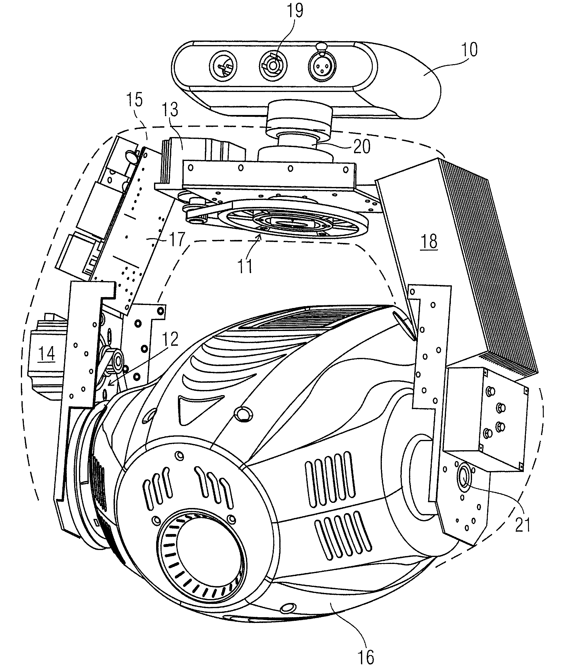
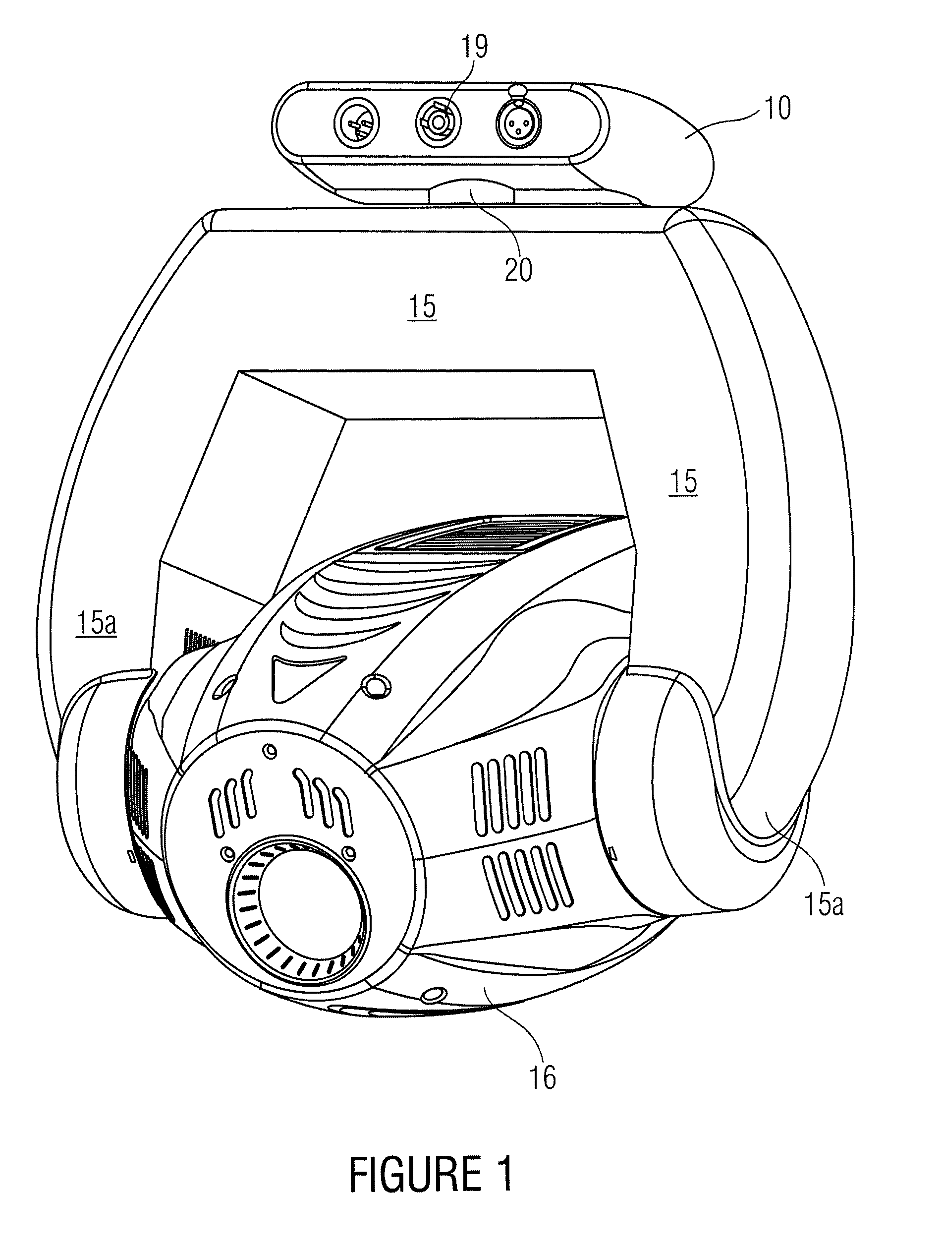
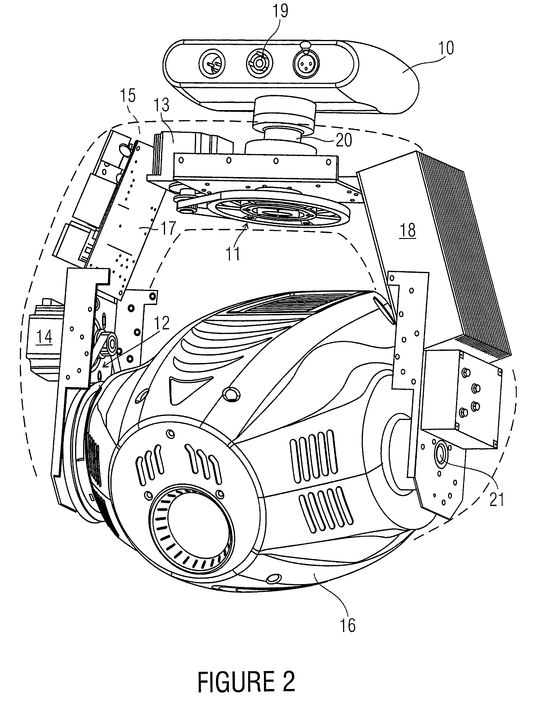
[0015]The invention is based on an implementation according to the prior art, as it is illustrated in FIG. 3. In this implementation, a comparatively large primitive element is provided, via which usually the mounting to a crossbar is performed. This device, just like the inventive device according to FIGS. 1 and 2, serves for influencing a light beam, i.e., for example influencing a light beam for stage, entertainment and spot il...


PUM


Abstract

The device for influencing a light beam includes a primitive element and a housing which is arranged at a rotatable arm and which is rotatable with respect to the primitive element by means of one of the several drive units, and into which a light source for generating a light beam may be introduced, wherein at least one control electronics for operating the device is arranged in the rotatable arm or in the housing.

Description

CROSS-REFERENCE TO RELATED APPLICATIONS[0001]This application is a national phase 371 entry of PCT / EP2007 / 002768 filed 28 Mar. 2007, which claims priority to German Patent Application No. 202006007047.8 filed 28 Apr. 2006.BACKGROUND OF THE INVENTION[0002]The invention relates to a device for influencing a light beam, in particular a light beam for stage, entertainment or spot illumination.[0003]Such devices are, for example, known as so-called moving heads and are basically arranged as illustrated in FIG. 3. An arm is rotatably mounted to a primitive element, to which in turn a housing is mounted, in which a light source is housed. From several drives, usually two drives, a rotation of the rotatable arm and the housing results. The two axes of rotation around which those movements take place are arranged in a right angle to each other. In the housing itself means may be provided by which the light beam of the light source housed in the housing is influenced, e.g. with regard to its ...

Claims


Application Information

Patent Timeline
Patent Type & Authority Patents(United States)
IPC IPC(8): F21V21/26
CPCF21V21/15F21V21/30F21V23/02F21V23/026F21W2131/406
Inventor SALM, MARKUSKUENZLER, UDO
Owner GLP GERMAN LIGHT PRODS
Why Eureka
Try Eureka