Temperature control circuit

a technology of temperature control circuit and temperature control, which is applied in the direction of temperatue control, process and machine control, instruments, etc., can solve the problem that the electronic devices cannot work properly

Inactive Publication Date: 2012-01-17
HON HAI PRECISION IND CO LTD
View PDF4 Cites 26 Cited by
  • Summary
  • Abstract
  • Description
  • Claims
  • Application Information

AI Technical Summary

Problems solved by technology

However, when the temperature is too low, such as 10 degrees below zero, some electronic devices cannot work properly.

Method used


Image

  • Temperature control circuit
  • Temperature control circuit
  • Temperature control circuit

Examples


Embodiment Construction

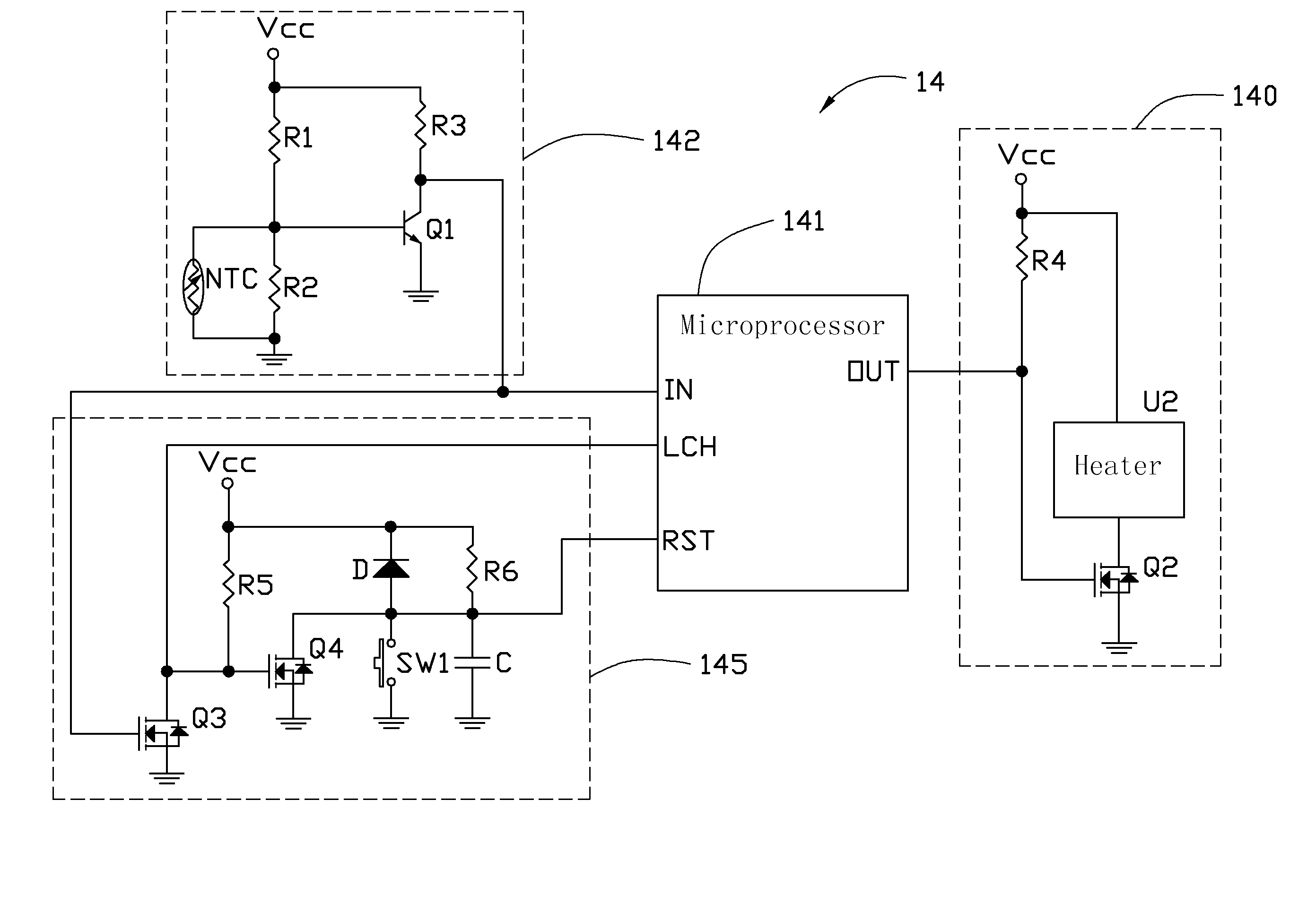
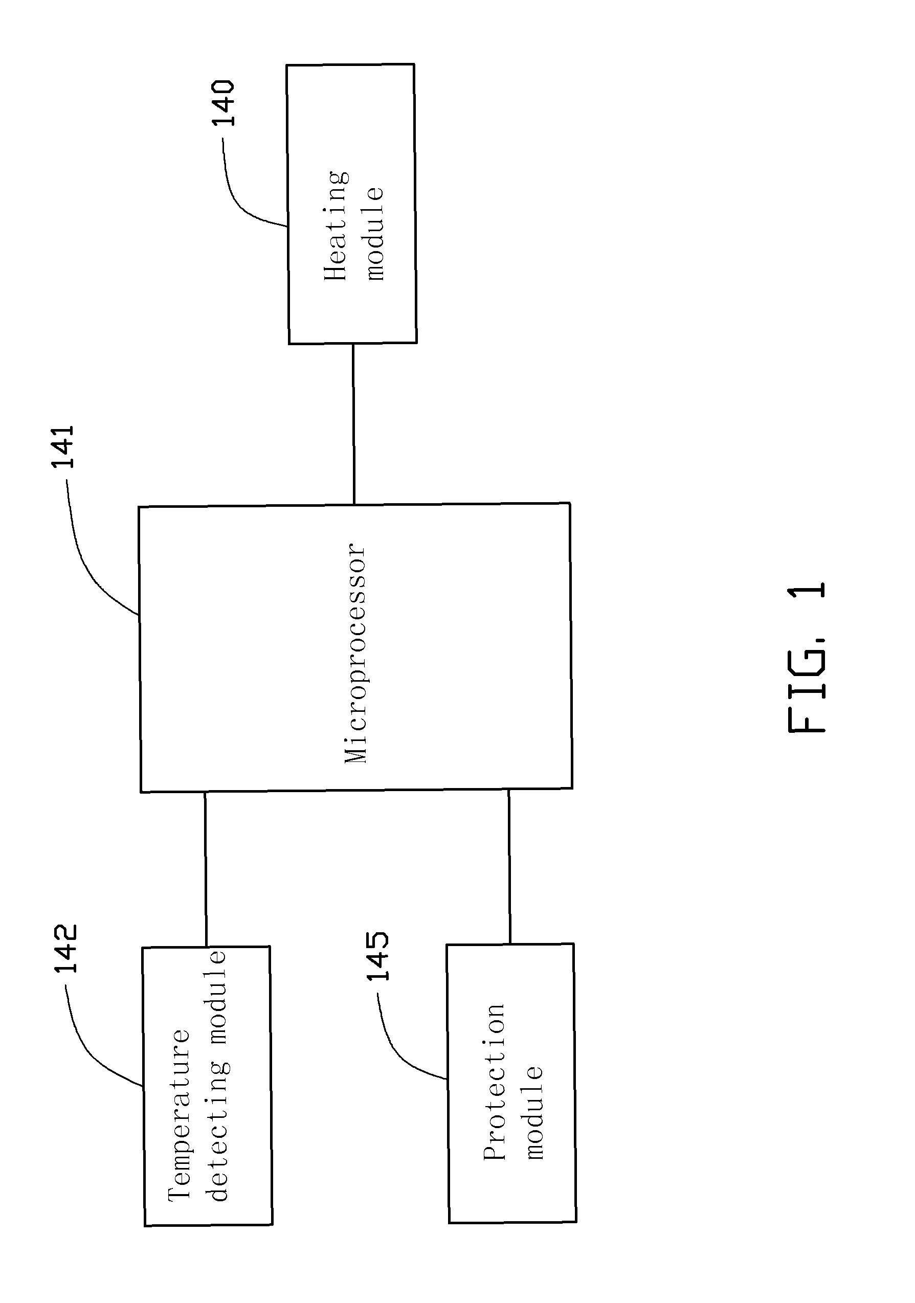
[0008]Referring to FIG. 1, an exemplary embodiment of a temperature control circuit 14 is used in an electronic device to make the electronic device operate properly. The temperature control circuit 14 includes a microprocessor 141, a heating module 140, a temperature detecting module 142, and a protection module 145. The heating module 140, the temperature detecting module 142, and the protection module 145 all connect to the microprocessor 141. When the electronic device powers on, the microprocessor 141 controls the heating module 142 to heat the electronic device. The temperature detecting module 142 detects the temperature of the electronic device for outputting a detection signal to the protection module 145 and the microprocessor 141. The protection module 145 controls a status of the microprocessor 141. The microprocessor 141 controls the heating module 140 to work or not to work according to the detection signal.

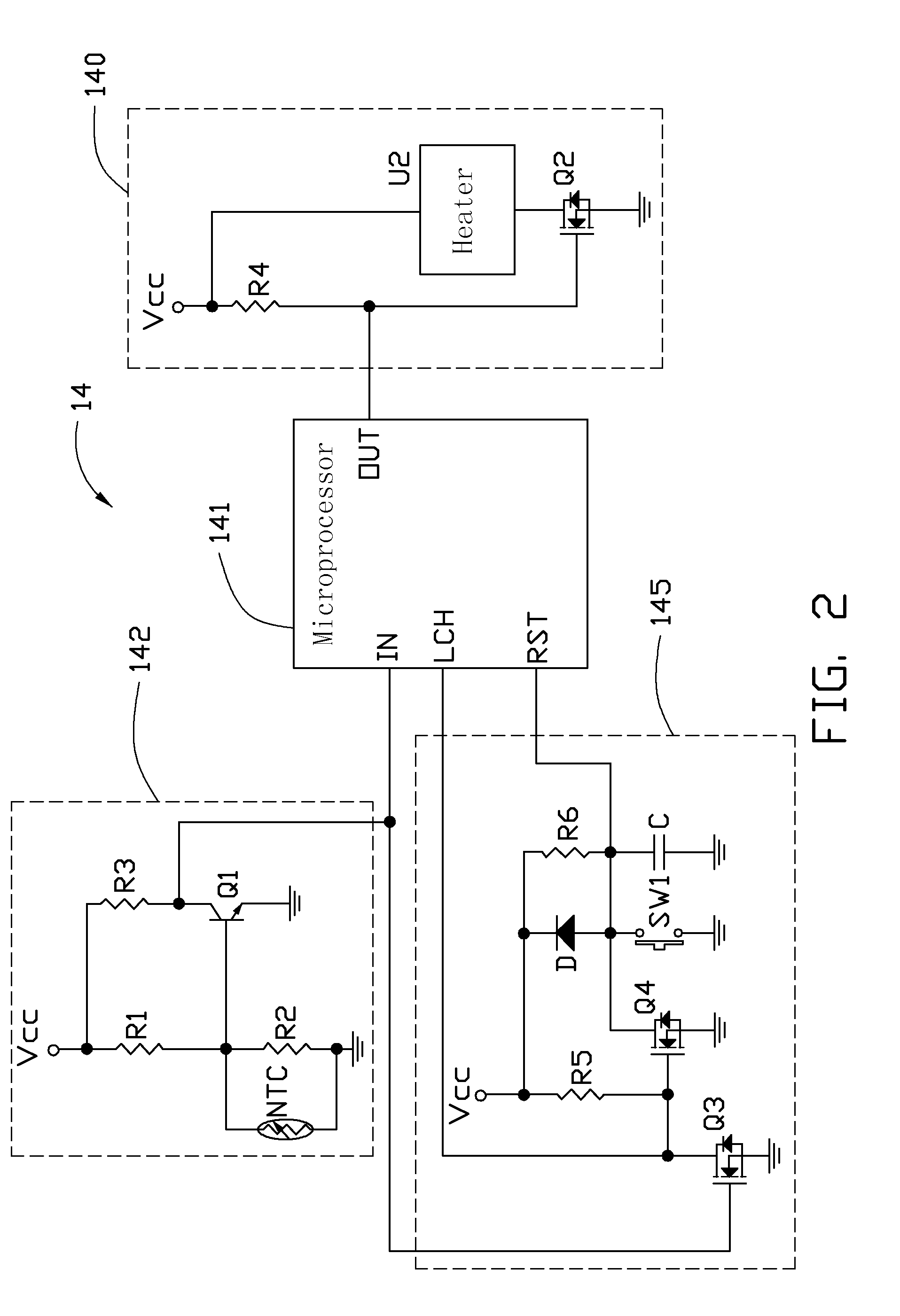
[0009]Referring to FIG. 2, the temperature detecting module 14...


PUM


Abstract

A temperature control circuit includes a microprocessor, a protection module, a temperature detecting module, and a heating module. The temperature detecting module includes a thermistor and a first switch. The thermistor is operable to sense a temperature to turn on or off the first switch for outputting a detection signal to the microprocessor and the protection module. The protection module is operable to control the microprocessor to work or reset according to the detection signal. The heating module includes a heater and a second switch. The microprocessor controls the second switch to turn on or off for making the heater work or stop working according to the detection signal.

Description

CROSS-REFERENCE TO RELATED APPLICATIONS[0001]Relevant subject matter is disclosed in two co-pending U.S. patent applications 12 / 755,402, and 12 / 755,400 filed on the same date and having the same title, which are assigned to the same assignee as this patent application.BACKGROUND[0002]1. Technical Field[0003]The present disclosure relates to a temperature control circuit.[0004]2. Description of Related Art[0005]When the temperature is within a range from 0 degrees Celsius to 70 degrees, most electronic devices operate properly. However, when the temperature is too low, such as 10 degrees below zero, some electronic devices cannot work properly. Therefore, an effective temperature control circuit is beneficial for control the working temperature for many electronic devices.BRIEF DESCRIPTION OF THE DRAWINGS[0006]FIG. 1 is a schematic block diagram of an exemplary embodiment of a temperature control circuit.[0007]FIG. 2 is a circuit diagram of the temperature control circuit in FIG. 1.D...

Claims


Application Information

Patent Timeline
Patent Type & Authority Patents(United States)
IPC IPC(8): H05B1/02
CPCG05D23/2413G05D23/1909G05D23/24
Inventor HSIEH, MING-CHIH
Owner HON HAI PRECISION IND CO LTD
Why Eureka
Try Eureka