Objective lens for endoscopes
a technology of endoscopes and lenses, applied in the field of objective lenses, can solve the problems of increasing the angle of view, and achieve the effect of compact design and favorable image quality
- Summary
- Abstract
- Description
- Claims
- Application Information
AI Technical Summary
Benefits of technology
Problems solved by technology
Method used
Image
Examples
embodiment 1
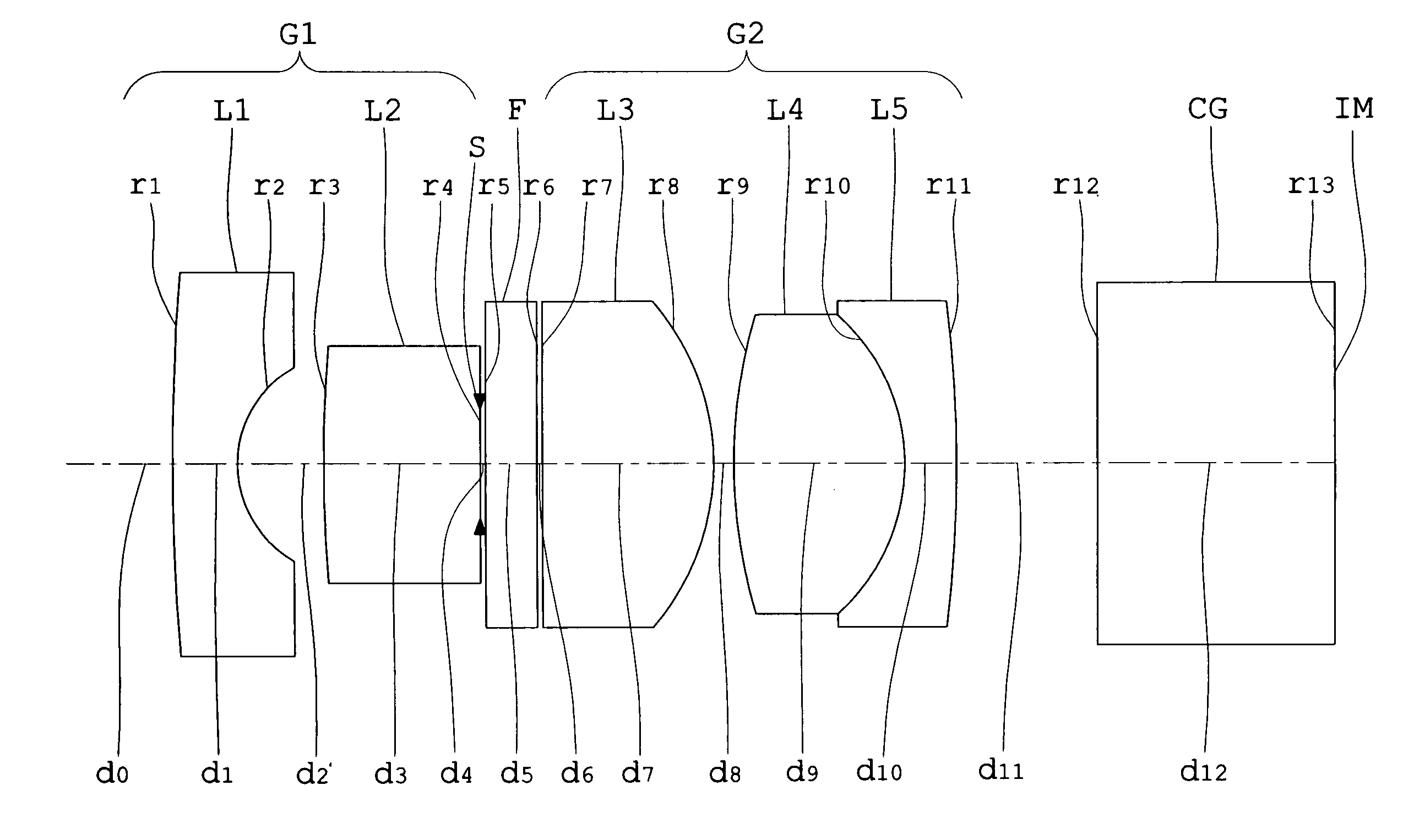
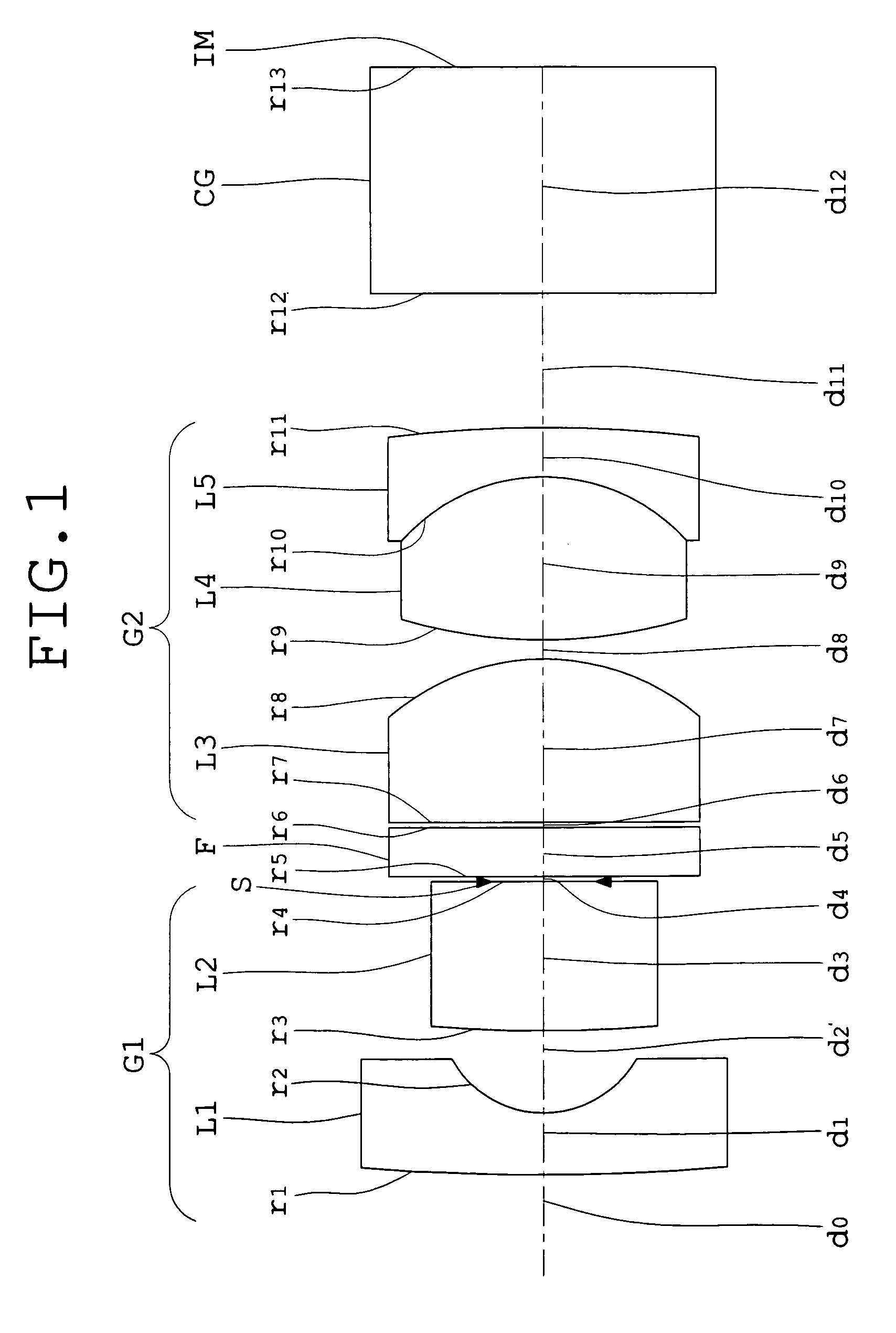
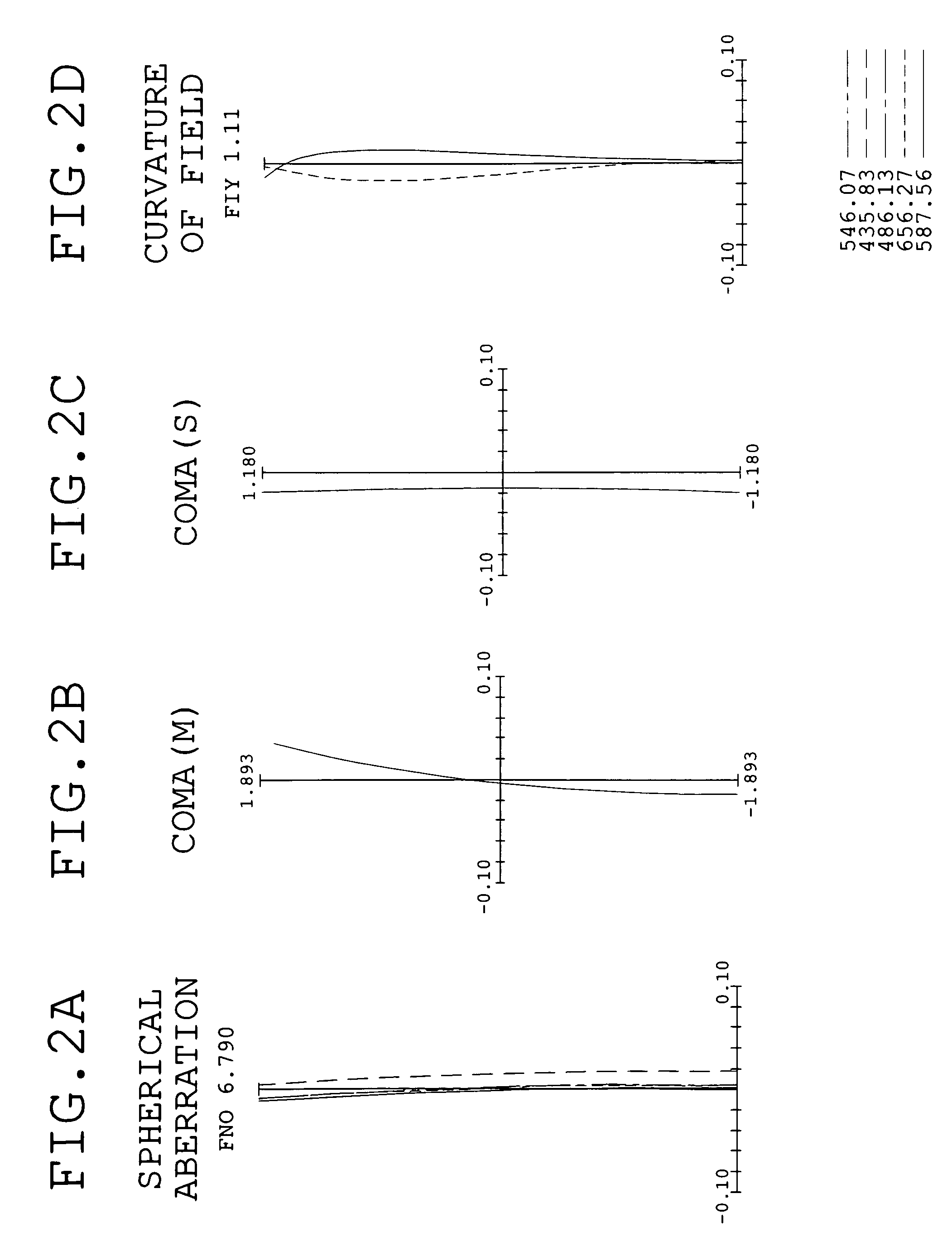
[0072]FIG. 1 is a sectional view showing an optical arrangement, developed along the optical axis, of the objective lens for endoscopes of Embodiment 1 according to the present invention. FIGS. 2A, 2B, 2C, and 2D are graphs showing spherical aberration, coma (meridional rays), coma (sagittal rays), and curvature of field, respectively, in the optical system of Embodiment 1.
[0073]The objective lens for endoscopes of Embodiment 1 has a front lens unit G1 and a rear lens unit G2 with an aperture stop S and a filter F between them. In FIG. 1, reference symbol CG denotes a cover glass and IM denotes an image plane. Here, the filter F is an infrared cutoff filter. In the objective lens for endoscopes of Embodiment 1, a part of a third lens element L3 whose center thickness is relatively large is replaced with the infrared cutoff filter and the replaced infrared cutoff filter is introduced into an objective optical system in such a way that it is interposed between the third lens element L...
embodiment 2
[0078]FIG. 3 is a sectional view showing an optical arrangement, developed along the optical axis, of the objective lens for endoscopes of Embodiment 2 according to the present invention. FIGS. 4A, 4B, 4C, and 4D are graphs showing spherical aberration, coma (meridional rays), coma (sagittal rays), and curvature of field, respectively, in the optical system of Embodiment 2.
[0079]The objective lens for endoscopes of Embodiment 2 has the front lens unit G1 and the rear lens unit G2 with the aperture stop S between them. In FIG. 3, reference symbol F denotes the filter, CG denotes the cover glass, and IM denotes the image plane. A fundamental arrangement of lens elements in each of the front lens unit G1 and the rear lens unit G2 is almost the same as in Embodiment 1. Also, Embodiment 2 is such that the infrared cutoff filter F is placed behind the rear lens unit G2. As described in Embodiment 1, the filter may be located at any position between the front lens unit G1 and the rear lens...
embodiment 3
[0082]FIG. 5 is a sectional view showing an optical arrangement, developed along the optical axis, of the objective lens for endoscopes of Embodiment 3 according to the present invention. FIGS. 6A, 6B, 6C, and 6D are graphs showing spherical aberration, coma (meridional rays), coma (sagittal rays), and curvature of field, respectively, in the optical system of Embodiment 3.
[0083]The objective lens for endoscopes of Embodiment 3 has the front lens unit G1 and the rear lens unit G2 with the aperture stop S between them. In FIG. 5, reference symbol CG denotes the cover glass and IM denotes the image plane.
[0084]A fundamental arrangement of lens elements in each of the front lens unit G1 and the rear lens unit G2 is almost the same as in Embodiment 1.
[0085]Subsequently, numerical data of optical members constituting the objective lens for endoscopes of Embodiment 3 are shown below.
[0086]
Numerical Embodiment 3Unit: mmSurface dataFaceRefractiveAbbe'sFace numberRadius of curvaturespacingin...
PUM
 Abstract
Description
Claims
Application Information
 - R&D
- Intellectual Property
- Life Sciences
- Materials
- Tech Scout
- Unparalleled Data Quality
- Higher Quality Content
- 60% Fewer Hallucinations
Browse by: Latest US Patents, China's latest patents, Technical Efficacy Thesaurus, Application Domain, Technology Topic, Popular Technical Reports.
© 2025 PatSnap. All rights reserved.Legal|Privacy policy|Modern Slavery Act Transparency Statement|Sitemap|About US| Contact US: help@patsnap.com


