Continuously variable transmission

a transmission and variable technology, applied in the direction of transportation and packaging, distribution equipment, hoisting equipment, etc., can solve the problems of inconvenient maintenance and operation, and inability to ensure stable rotation

Active Publication Date: 2012-01-24
TOYOTA JIDOSHA KK
View PDF66 Cites 17 Cited by
  • Summary
  • Abstract
  • Description
  • Claims
  • Application Information

AI Technical Summary

Benefits of technology

[0008]The invention provides a continuously variable transmission in which a sliding member can be maintained in an optimum position.
[0010]In the continuously variable transmission of such a configuration, because the working oil is more difficult to discharge from the second oil passage than from the first oil passage, an oil pressure is supplied between the sliding member and shaft even in a case where the pressure inside the hydraulic chamber is reduced. As a result, the sliding member can be prevented from inclining.
[0012]In this case, the working oil moves from the side close to the belt for power transmission to the side that is far therefrom, and the sliding member can be prevented more effectively from inclining.

Problems solved by technology

However, the problem associated with the configurations disclosed in JP-A-2006-64008, JP-A-2006-300270, and JP-A-2007-192375 is that a sliding member inclines and stable rotation is difficult to ensure when the pressure inside a hydraulic chamber is decreased.

Method used


Image

  • Continuously variable transmission
  • Continuously variable transmission
  • Continuously variable transmission

Examples


Embodiment Construction

[0018]Embodiments of the invention will be described below with reference to the appended drawings. In the below-described embodiments, identical or corresponding components will be assigned with identical reference numerals and explanation thereof will not be repeated.

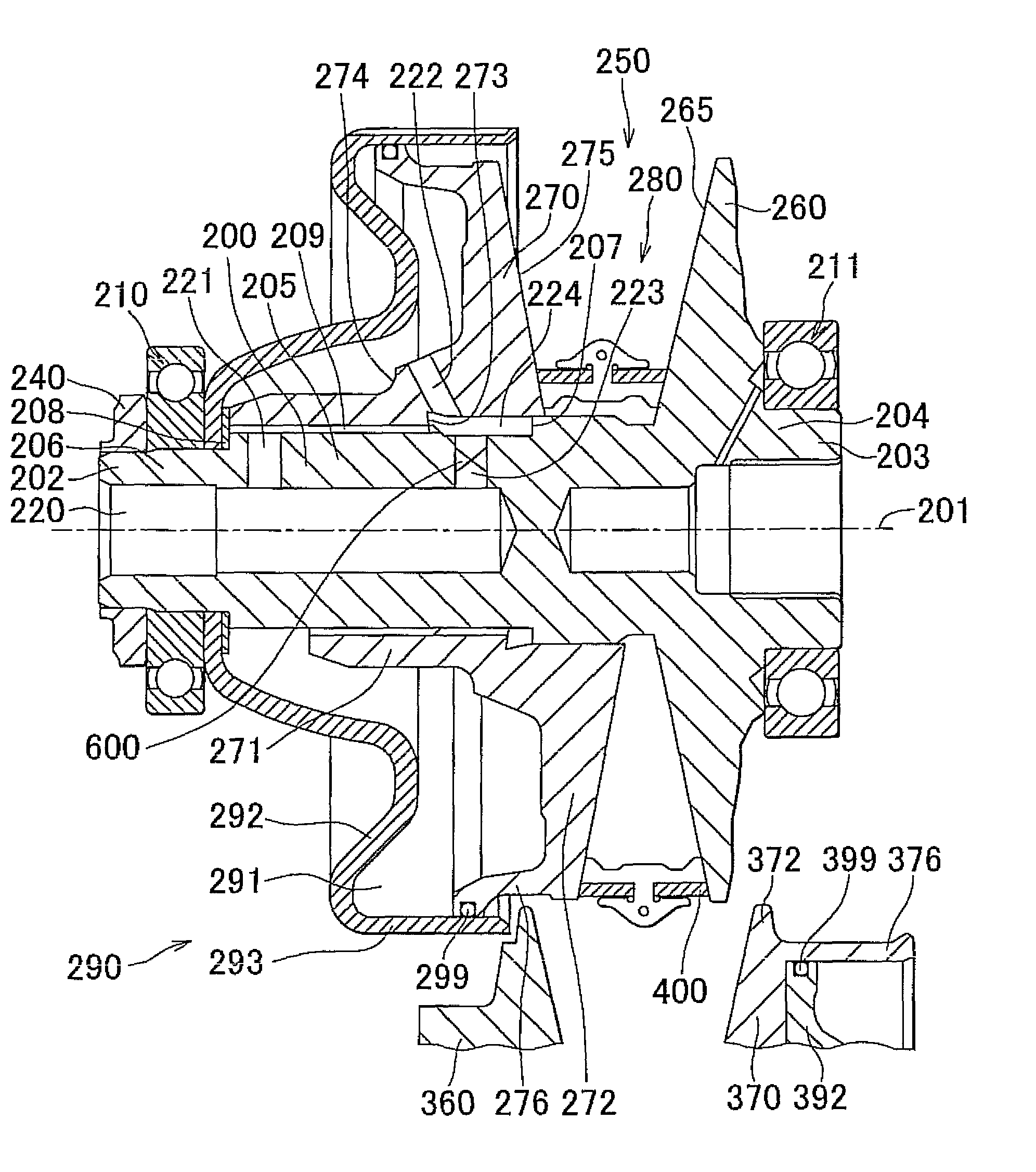
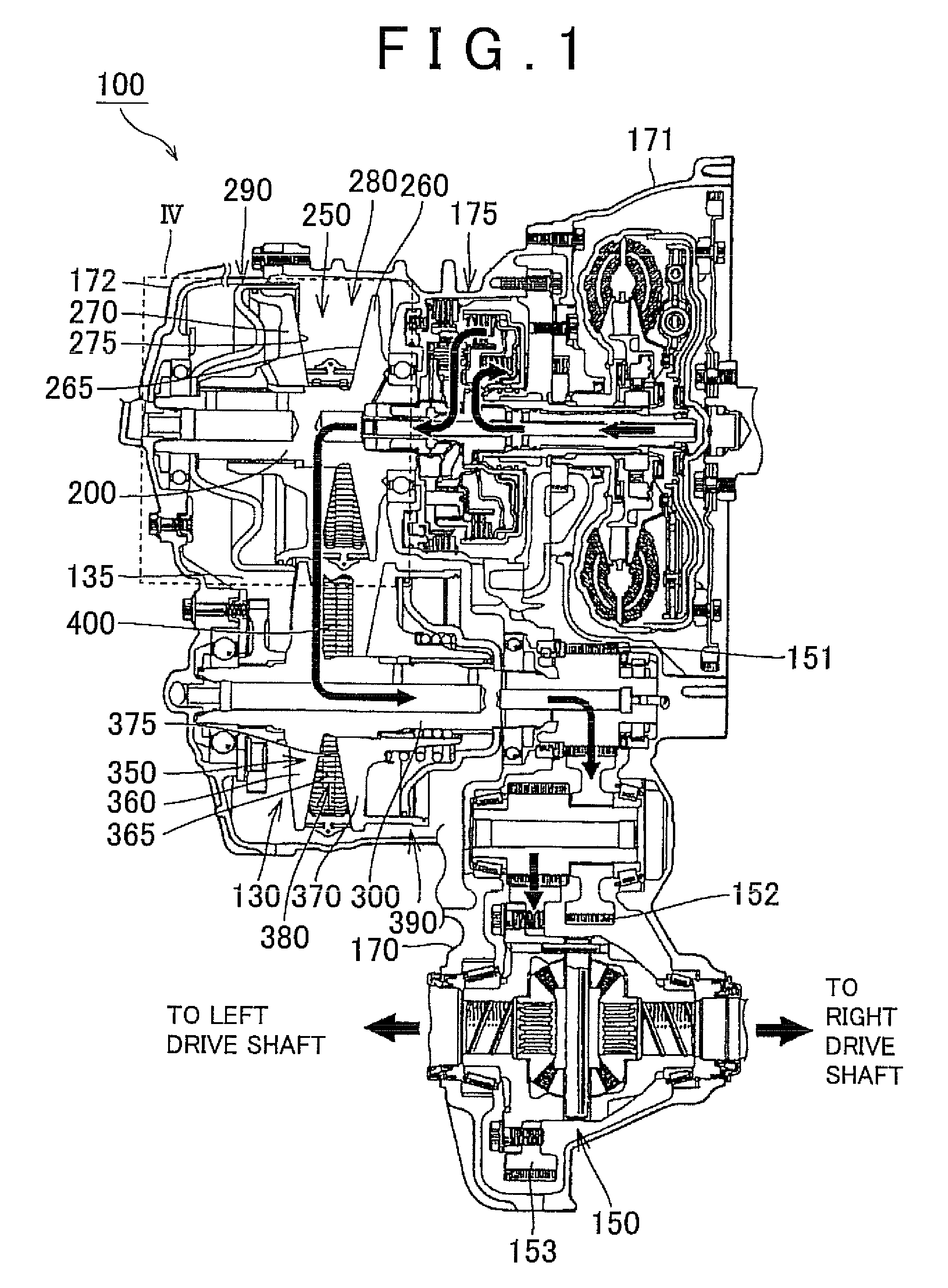
[0019]FIG. 1 is a cross-sectional schematic diagram illustrating the configuration of a continuously variable transmission according to Embodiment 1 of the invention. A belt-type continuously variable transmission 100 shown in FIG. 1 is installed on a vehicle such as an automobile. The continuously variable transmission 100 is provided with a transmission mechanism unit 130.

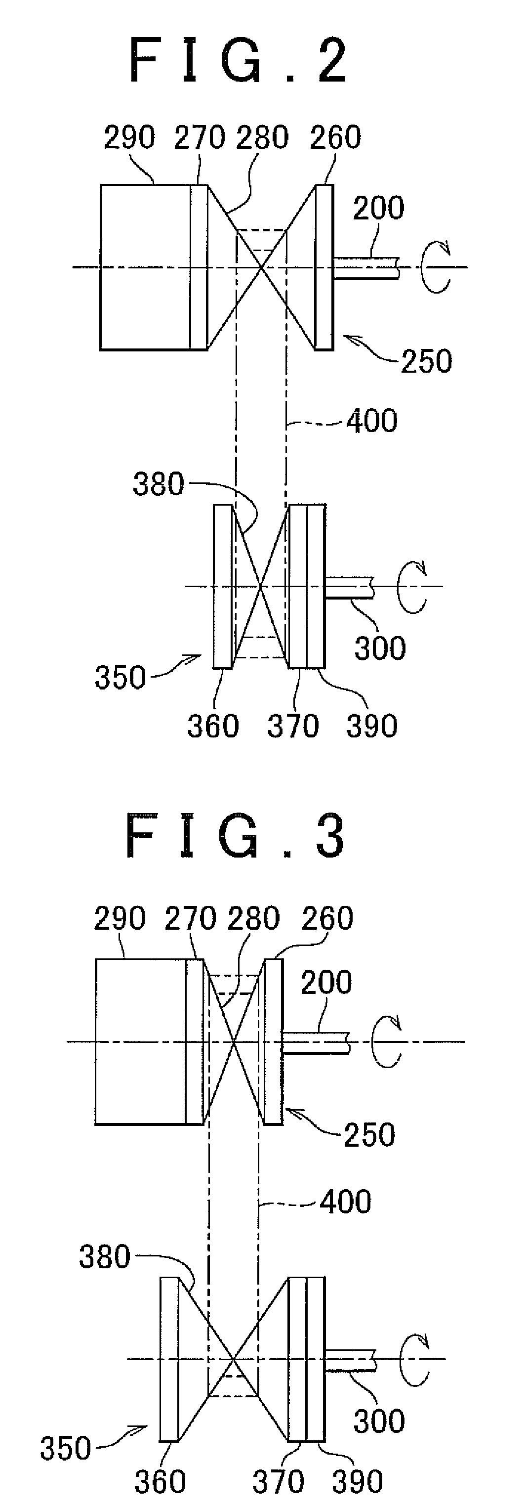
[0020]The transmission mechanism unit 130 includes a primary shaft 200 on a drive side (input side) that inputs a torque from an engine, a secondary shaft 300 on a driven side (output side) that outputs the torque, a primary pulley 250 that is provided at the primary shaft 200, and a secondary pulley 350 that is provided at the secondary shaft 300....


PUM


Abstract

A continuously variable transmission in which a sliding member is prevented from inclining is provided. The continuously variable transmission has a first oil passage provided in a movable sheave, and a second oil passage provided in a primary shaft supporting the movable sheave and connected in series to the first oil passage. A working oil is discharged from a hydraulic chamber via the first and second oil passages. The working oil is more difficult to discharge from the second oil passage than the first oil passage.

Description

INCORPORATION BY REFERENCE[0001]The disclosure of Japanese Patent Application No. 2008-142986 filed on May 30, 2008 including the specification, drawings and abstract is incorporated herein by reference in its entirety.BACKGROUND OF THE INVENTION[0002]1. Field of the Invention[0003]The invention relates to a continuously variable transmission, and more specifically to a continuously variable transmission in which speed change is performed by changing the width of a variable speed pulley.[0004]2. Description of the Related Art[0005]A continuously variable transmission is disclosed, for example, in Japanese Patent Application Publication No. 2006-64008 (JP-A-2006-64008), Japanese Patent Application Publication No. 2006-300270 (JP-A-2006-300270), and Japanese Patent Application Publication No. 2007-192375 (JP-A-2007-192375).[0006]JP-A-2006-64008 discloses an example of a belt-type continuously variable transmission structure. JP-A-2006-300270 discloses a valve that inhibits the dischar...

Claims


Application Information

Patent Timeline
Patent Type & Authority Patents(United States)
IPC IPC(8): F16H59/00F16H55/56F16H63/00F16H61/00
CPCF16H63/065F16H55/56
Inventor YAMAGUCHI, KENICHIKONDO, HIROKI
Owner TOYOTA JIDOSHA KK
Why Eureka
Try Eureka