Separating apparatus for a cleaning appliance

a technology for cleaning appliances and separating equipment, which is applied in the direction of filter regeneration, dispersed particle filtration, and using liquid separation agents, etc., can solve the problems of user inadvertent operation of the wrong catch, difficulty in removing dirt and dust, and the need for dirt and dust to be separated from the airflow

Active Publication Date: 2012-01-24
DYSON TECH LTD
View PDF8 Cites 159 Cited by
  • Summary
  • Abstract
  • Description
  • Claims
  • Application Information

AI Technical Summary

Benefits of technology

[0009]By presenting the user with only one releasable catch at a time, the user automatically operates those catches in the correct sequence—namely the catch for releasing the closure member and emptying dirt from the separating apparatus, followed by the catch for releasing the collecting chamber from the separator, if required. The invention prevents the user from accidentally releasing the collecting chamber from the separator when it was the user's intention simply to empty dirt and dust from the collecting chamber.
[0010]Preferably, the second releasing means is at least partially obscured when the first catch is engaged, so that the user is not confused by being presented with more than one catch.

Problems solved by technology

This causes dirt and dust to be separated from the airflow.
The absence of a bag in a cyclonic vacuum cleaner can create difficulties for the disposal of the dirt and dust which is collected by the cleaner.
Often it may be necessary for the user to dislodge the dirt manually, which can be inconvenient.
A problem which may be encountered with this type of arrangement is that the user may inadvertently operate the wrong catch.
This can be frustrating and confusing for the user and may result in dirt and dust spilling out of the collecting chamber.

Method used


Image

  • Separating apparatus for a cleaning appliance
  • Separating apparatus for a cleaning appliance
  • Separating apparatus for a cleaning appliance

Examples


Embodiment Construction

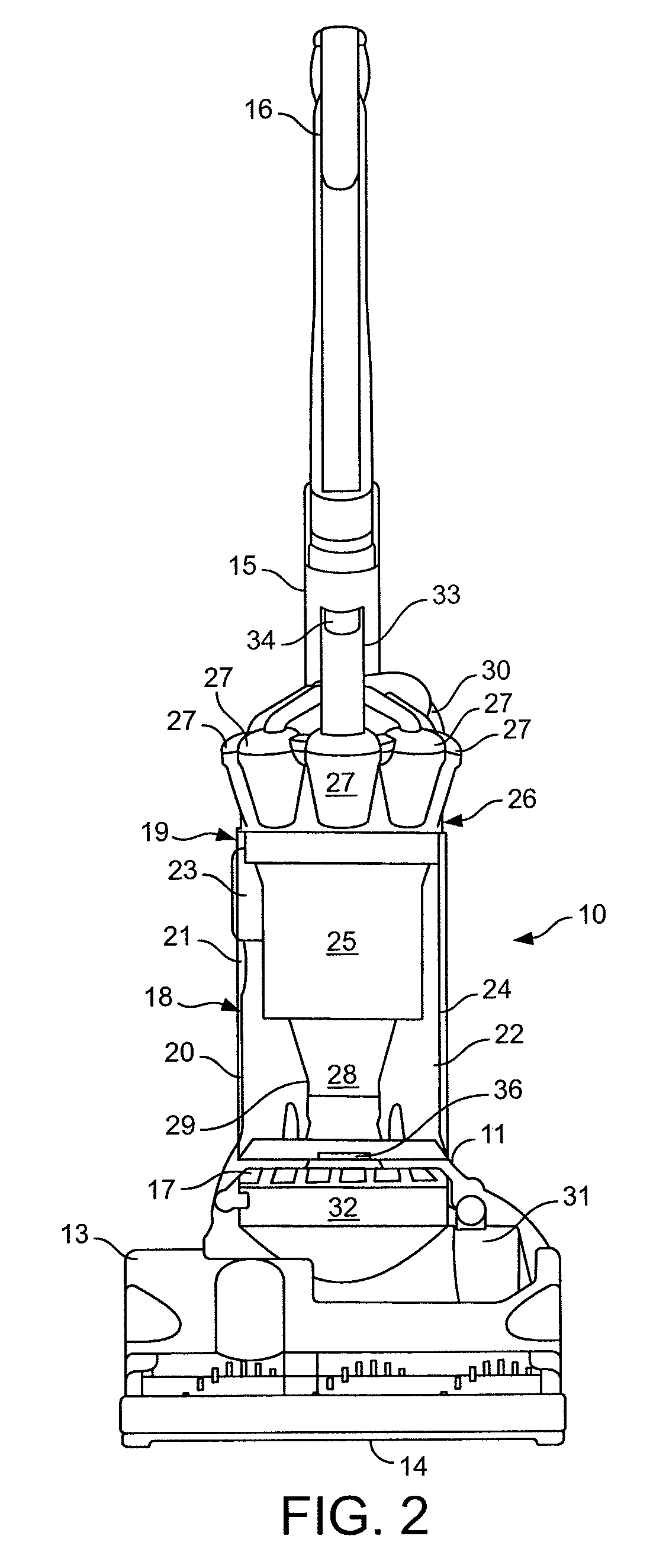
[0031]With reference to FIGS. 2 and 3a, an upright vacuum cleaner is shown and indicated generally by the reference numeral 10. The vacuum cleaner 10 comprises a main body 11 which includes a motor and fan unit (not shown) and a pair 12 of wheels. A cleaner head 13 is pivotably mounted on the lower end of the main body 11 and a dirty air inlet 14 is provided in the underside of the cleaner head 13 facing the floor surface. The main body 11 further includes a spine 15 which extends vertically upward and merges into a hand grip 16. The hand grip 16 can be manipulated by a user to manoeuvre the vacuum cleaner 10 across a floor surface. The main body 11 further includes outlet ports 17 for exhausting air from the vacuum cleaner 10.

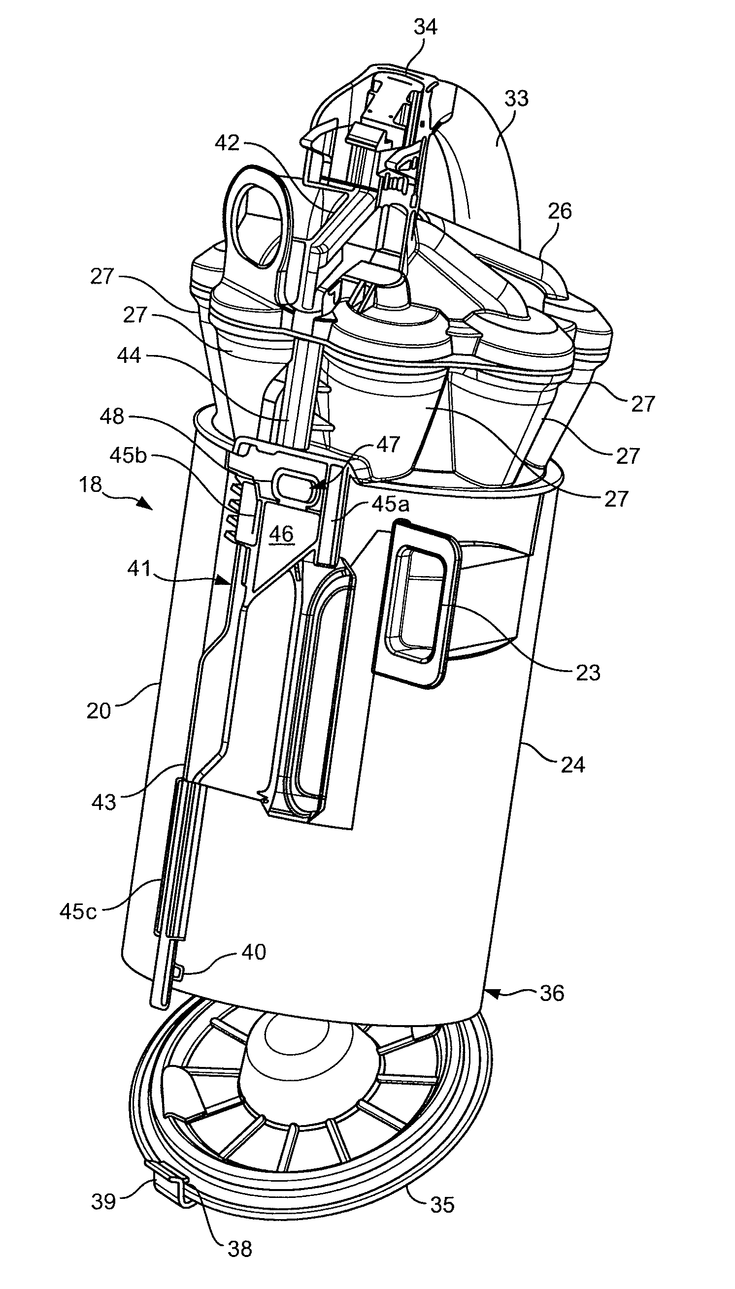
[0032]Separating apparatus 18 is releasably held on the main body 11 of the vacuum cleaner 10. The separating apparatus 18 comprises a separator 19 and a collecting chamber 20. The separating apparatus 18 is supported on the main body 11 above the outlet ports...


PUM

PropertyMeasurementUnit
opening forceaaaaaaaaaa
timeaaaaaaaaaa
diameteraaaaaaaaaa

Abstract

A separating apparatus for a cleaning appliance, such as a vacuum cleaner, includes a separator for separating dirt and dust from a fluid flow and a collecting chamber arranged to collect dirt and dust separated by the separator. A first catch for opening a closure member on the collecting chamber is provided, with first releasing means for releasing this catch. There is also provided a second catch for releasing the collecting chamber from the separator and second releasing means for releasing the second catch. The second releasing means is inaccessible when the first catch is engaged. A cover associated with the first releasing means obscures the second releasing means until the first catch has been released. The invention prevents the user from accidentally releasing the collecting chamber from the separator when it was the user's intention simply to empty dirt and dust from the collecting chamber.

Description

REFERENCE TO RELATED APPLICATIONS[0001]This application claims the priority of United Kingdom application No. 0902199.9, filed Feb. 11, 2009 and GB0821827.3, filed Nov. 28, 2008, the entire contents of which are incorporated herein by reference.FIELD OF THE INVENTION[0002]The present invention relates to separating apparatus for a cleaning appliance such as a vacuum cleaner.BACKGROUND OF THE INVENTION[0003]Vacuum cleaners which utilise cyclonic separators are known. In a typical cyclonic vacuum cleaner, an airflow in which dirt and dust is entrained enters a first cyclonic separator via a tangential inlet which causes the airflow to follow a spiral or helical path within a collecting chamber. This causes dirt and dust to be separated from the airflow. Relatively clean air passes out of the chamber while the separated dirt and dust is collected therein. In some appliances, the airflow is then passed to a second cyclonic separator stage which is capable of separating finer dirt and du...

Claims


Application Information

Patent Timeline
Patent Type & Authority Patents(United States)
IPC IPC(8): B01D45/12
CPCA47L9/1625A47L9/1641A47L9/1683A47L9/1691B04C5/185Y10S55/03A47L5/28A47L5/36A47L9/16B04C5/187
Inventor ASHBEE, GILESDYSON, JAMES
Owner DYSON TECH LTD
Why Eureka
Try Eureka