
Method and apparatus for sorting particles

a particle and sorting technology, applied in the field of particle sorting system, to achieve the effect of reducing error rate, increasing sorting rate, and low cos

Inactive Publication Date: 2011-01-13
CYTONOMEST
View PDF99 Cites 30 Cited by
  • Summary
  • Abstract
  • Description
  • Claims
  • Application Information

AI Technical Summary

Benefits of technology

The system achieves high-throughput sorting with reduced error rates and lower costs by effectively deflecting particles based on detected characteristics, enabling efficient sorting of large volumes of particles while minimizing interference between modules.

Problems solved by technology

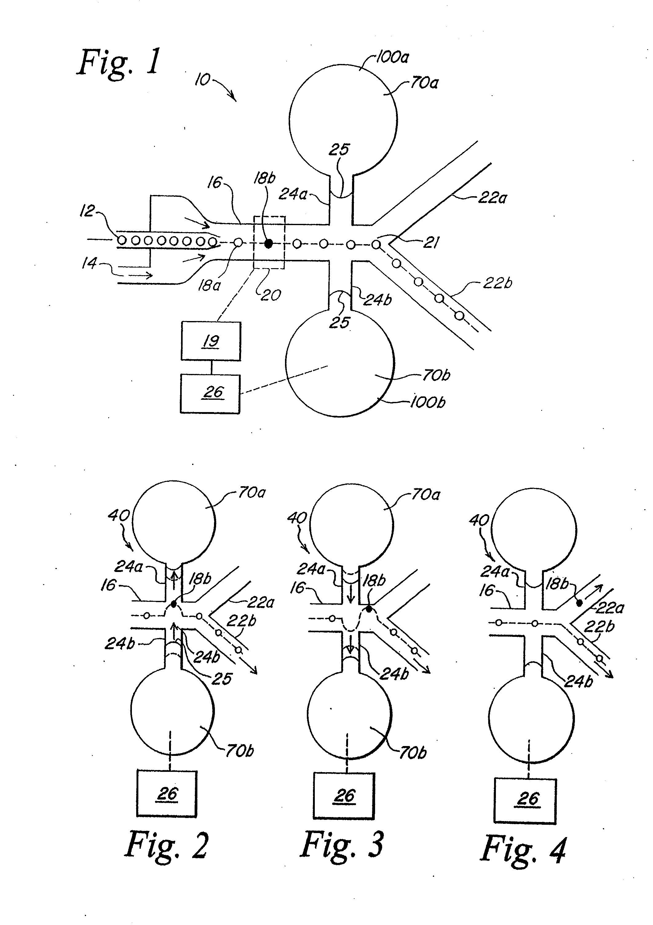
When the external actuator is activated, the pressure in the reservoir of the activated bubble valve increases, deflecting the meniscus and causing a flow disturbance in the measurement duct to deflect the flow therein.

Method used


Image

  • Method and apparatus for sorting particles
  • Method and apparatus for sorting particles
  • Method and apparatus for sorting particles

Examples


Embodiment Construction

[0037]The present invention provides a particle sorting system for sorting particles suspended in a liquid. The particle sorting system provides high-throughput, low error sorting of particles based on a predetermined characteristic. The present invention will be described below relative to illustrative embodiments. Those skilled in the art will appreciate that the present invention may be implemented in a number of different applications and embodiments and is not specifically limited in its application to the particular embodiments depicted herein.

[0038]The terms “duct”“channel” and “flow channel” as used herein refers to a pathway formed in or through a medium that allows for movement of fluids, such as liquids and gases. The channel in the microfluidic system preferably have cross-sectional dimensions in the range between about 1.0 μm and about 500 μm, preferably between about 25 μm and about 250 μm and most preferably between about 50 μm and about 150 μm. One of ordinary skill ...


PUM


Abstract

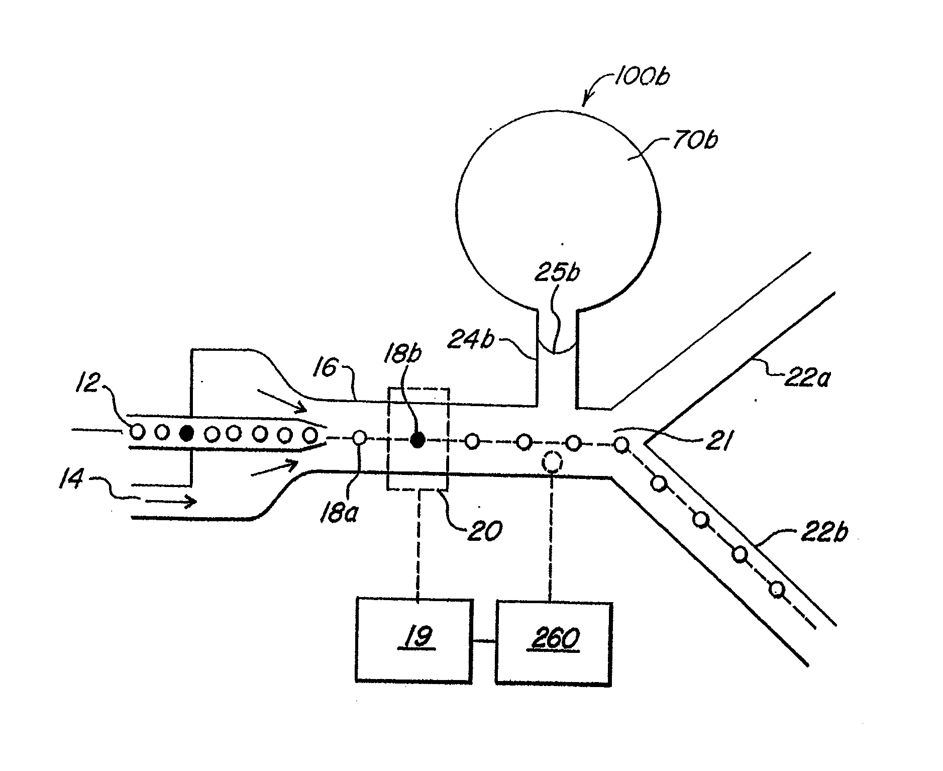
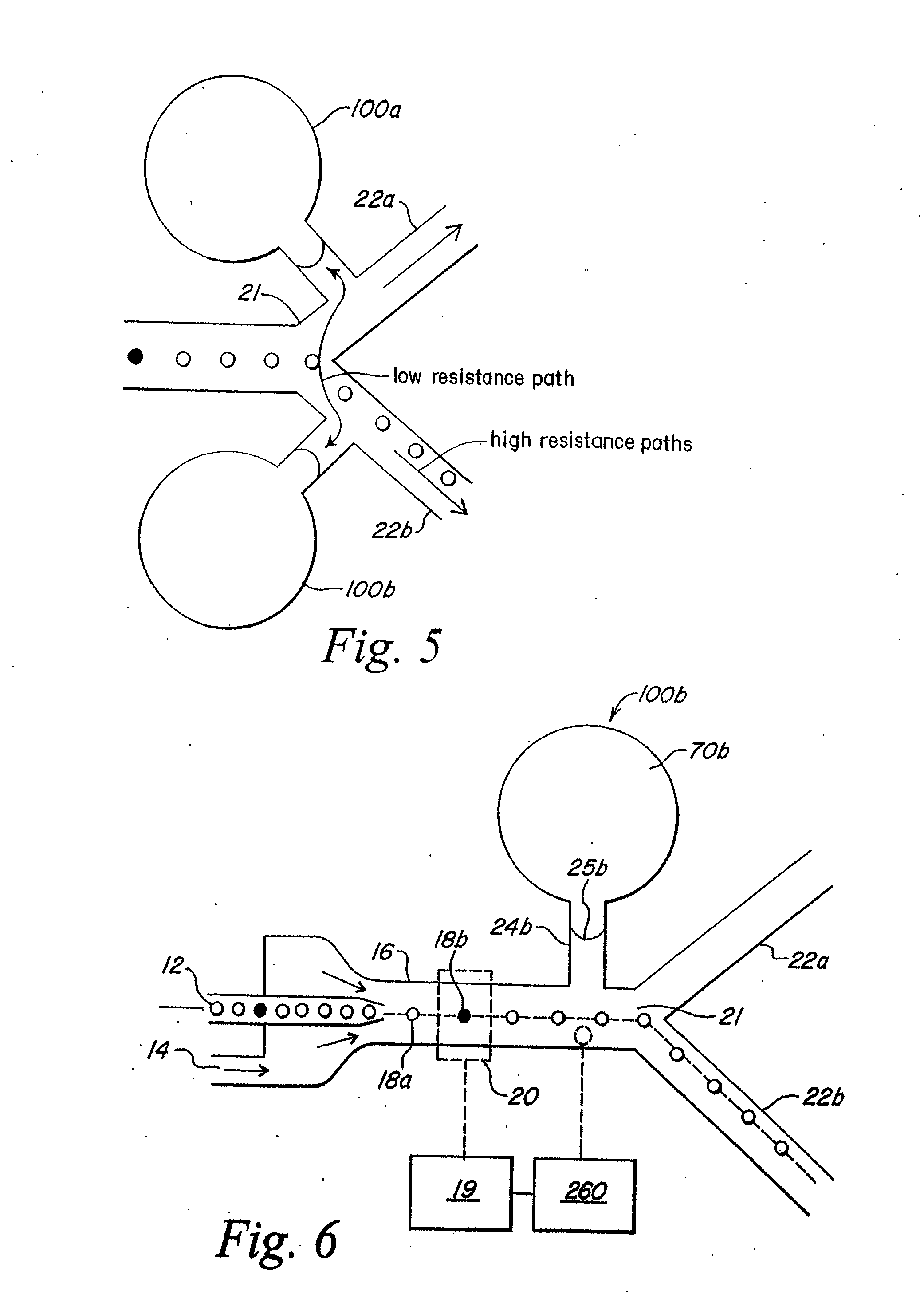
A method and apparatus for sorting particles moving through a closed channel system of capillary size comprises a bubble valve for selectively generating a pressure pulse to separate a particle having a predetermined characteristic from a stream of particles. The particle sorting system may further include a buffer for absorbing the pressure pulse. The particle sorting system may include a plurality of closely coupled sorting modules which are combined to further increase the sorting rate. The particle sorting system may comprise a multi-stage sorting device for serially sorting streams of particles, in order to decrease the error rate.

Description

RELATED APPLICATIONS[0001]This application is a continuation of U.S. patent application Ser. No. 11 / 603,444 entitled “Method and Apparatus for Sorting Particles” filed Nov. 22, 2006, which claims priority to U.S. patent application Ser. No. 10 / 664,587 filed Sep. 16, 2003, which claims priority to U.S. Provisional Patent Application Ser. No. 60 / 411,143 filed Sep. 16, 2002, and U.S. Provisional Patent Application Ser. No. 60 / 411,058, filed Sep. 16, 2002, the contents of each of these applications are herein incorporated by reference. The present application also claims priority to, and is a continuation-in-part of, U.S. patent application Ser. No. 10 / 179,488, filed Jun. 24, 2002, which claims priority to U.S. Provisional Patent Application Ser. No. 60 / 373,256 filed Apr. 17, 2002 and U.S. patent application Ser. No. 10 / 329,008, filed Dec. 23, 2002, which claims priority to U.S. Provisional Patent Application Ser. No. 60 / 411,058 filed Sep. 16, 2002, the contents of each of the applicati...

Claims


Application Information

Patent Timeline
Patent Type & Authority Applications(United States)
IPC IPC(8): B03B5/00
CPCB01L3/502761B01L3/502776B01L2200/0636B01L2200/0647G01N2015/149B01L2300/0864B01L2400/0487G01N15/1459B01L2300/0816G01N15/149
Inventor BOHM, SEBASTIANGILBERT, JOHN R.DESHPANDE, MANISH
Owner CYTONOMEST
Learn More