
MAC layer timestamping approach for emerging wireless sensor platform and communication architecture

a wireless sensor and communication architecture technology, applied in the field of mac-layer timestamping in wireless sensor platforms, can solve the problems of inability to run interrupt handlers, inability to adapt to and inability to apply mac-layer timestamping approaches to the wsn with the new hardware and new 802.15.4 stacks, etc., to achieve the effect of reducing performance overhead

Inactive Publication Date: 2012-01-24
SAMSUNG ELECTRONICS CO LTD
View PDF5 Cites 5 Cited by
  • Summary
  • Abstract
  • Description
  • Claims
  • Application Information

AI Technical Summary

Benefits of technology

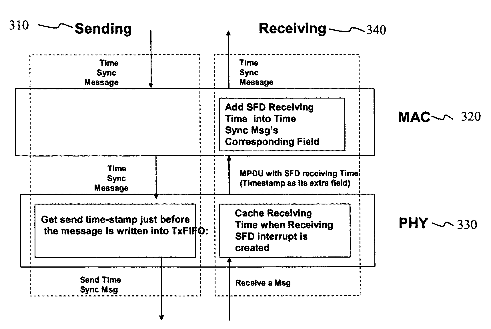
The present invention provides an improved method and apparatus for MAC-layer timestamping in a wireless network. The method involves capturing a receiving timestamp when a message is received at a physical layer of a wireless sensor node, and inserting the timestamp into a timestamping field of a medium access control protocol data unit (MPDU) packet. The MPDU packet is then transmitted to a time synchronization module (TSM) of the wireless sensor node. The TSM generates a time synchronization message with the embedded sending timestamp and sends it out from the wireless sensor node. The technical effects of the invention include improved accuracy and reliability in time synchronization, compatibility with new software and hardware platform, and minimal performance overhead.

Problems solved by technology

The existing approaches for MAC-layer times-stamping are not applicable to the WSN with the new hardware and new 802.15.4 stack.
In addition, traditional MAC-layer stamping approaches have been only tested on the application with one single Time Synchronization module, not in a large software system with multiple modules and multiple messaging.
The traditional MAC-layer stamping approach is not scalable.
In this case, the code needed to run in the interrupt handlers will be too large, the interrupts will be lost or queued, which eventually affects the whole system stability and results in node hanging in the worst case.

Method used


Image

  • MAC layer timestamping approach for emerging wireless sensor platform and communication architecture
  • MAC layer timestamping approach for emerging wireless sensor platform and communication architecture
  • MAC layer timestamping approach for emerging wireless sensor platform and communication architecture

Examples


Embodiment Construction

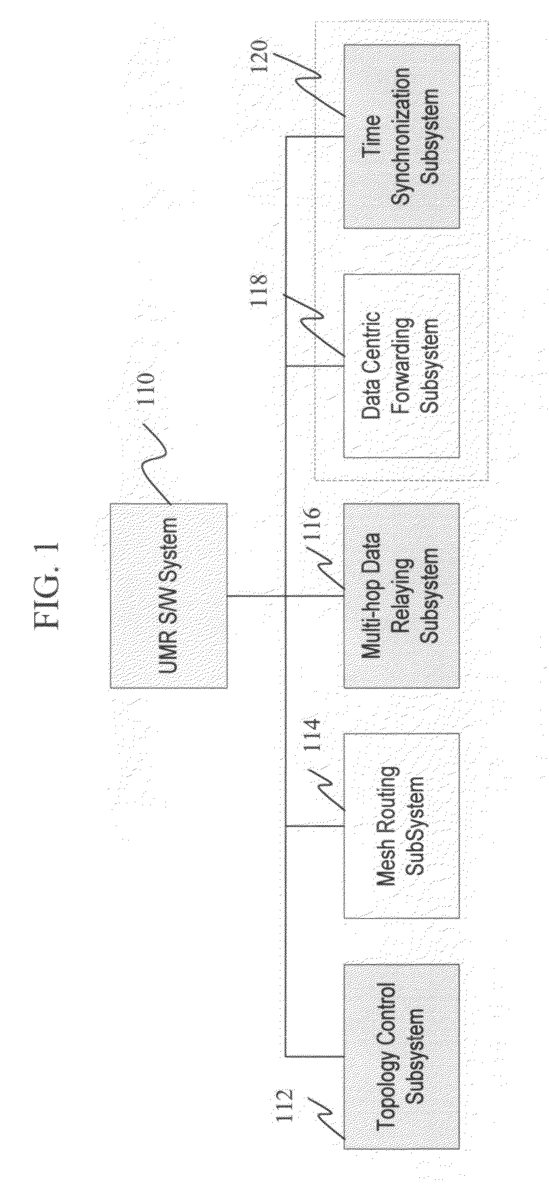
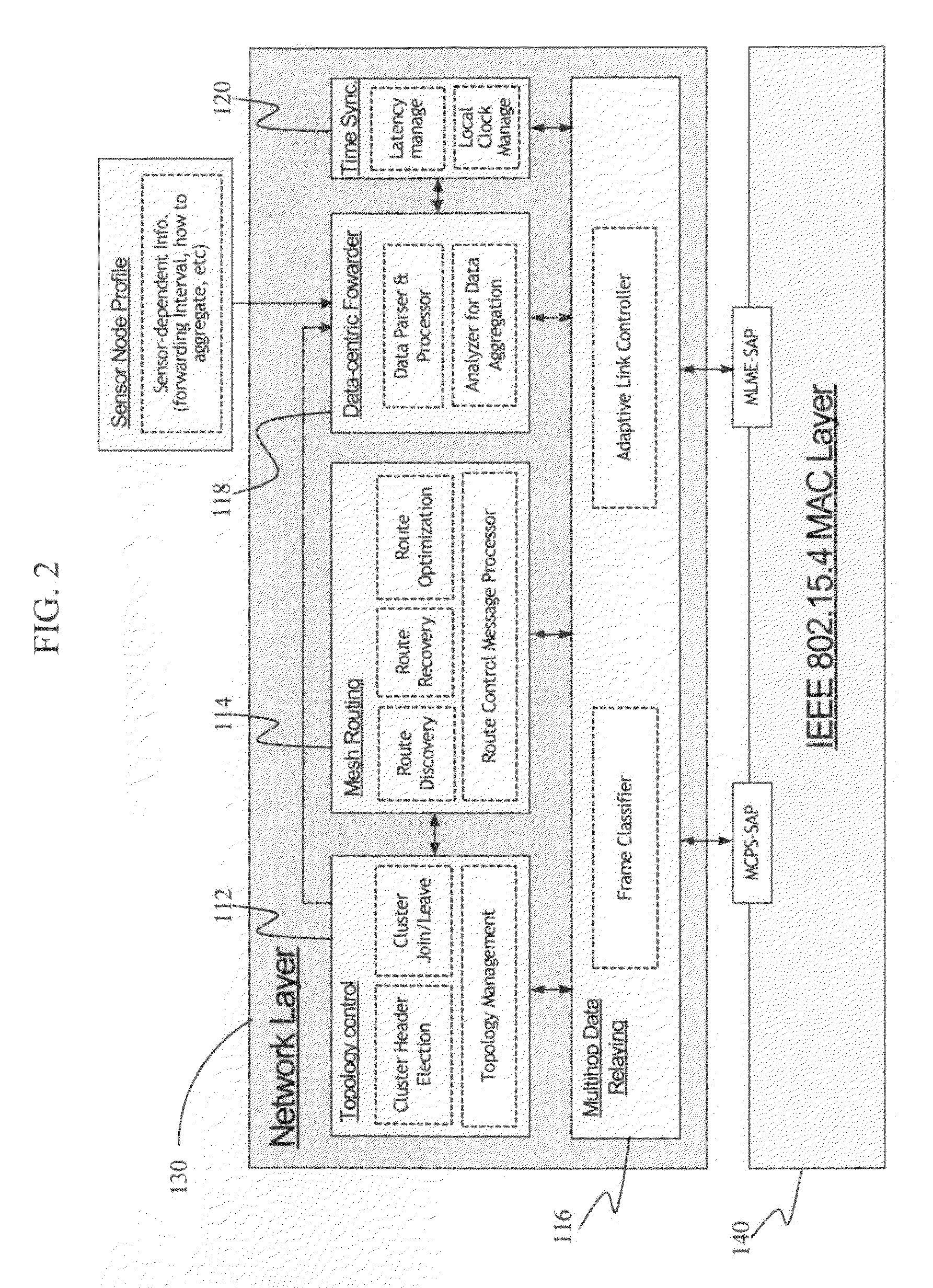
[0029]FIG. 1 schematically illustrates the block architecture of a Ubiquitous Sensor Network (USN) Mesh / Relay (UMR) software system we implemented in a sensor node. The UMR software system is developed for USN to provide intelligent, efficient, reliable and scalable USN networking framework using Topology control, Mesh Routing, Multi-hop Data Relaying, Data Centric Forwarding, and Time Synchronization based on IEEE 802.15.4 and TinyOS technologies. As shown in FIG. 1, a sensor node is constructed with UMR software system 110. Network Topology Control module 112 is in charge of topology formation and connectivity of sensor nodes, and provides the topology information that will be used by Mesh Routing module 114 of the sensor network. Mesh Routing module 114 is in charge of the route discovery, recovery and optimization. Multi-hop Data Relaying module 116 is in charge of the classification of Medium Access Control (MAC) frames and Adaptive Link Control (ALC) between sensor nodes. Thes...


PUM


Abstract

In the receiving side MAC layer timestamping approach, the MPDU structure is changed by adding an extra timestamping field. When a MPDU packet is generated, a captured receiving timestamp is written into the MPDU's timestamp field. The MPDU packet is then forwarded from the PHY to the MAC layer of the wireless sensor node. In the MAC layer, the receiving timestamp is further processed and inserted into a corresponding field of the time synchronization message, which is in turn transmitted to a Time Synchronization module. In the sending side MAC layer timestamping approach, the sending timestamp is captured immediately before the time synchronization message is written into TxFIFO.

Description

BACKGROUND OF THE INVENTION[0001]1. Field of the Invention[0002]The present invention relates to methods and apparatus for MAC-layer timestamping in a wireless sensor platform.[0003]2. Description of the Related Art[0004]The present invention incorporates by reference the following publications:[0005][1] IEEE Standard for Information technology, Part 15.4: Wireless Medium Access Control (MAC) and Physical Layer (PHY) Specifications for Low-Rate Wireless Personal Area Networks (WPANs); and[0006][2] Time Synchronization Module S / W Detailed Level Design Version 1.1 by Samsung Telecommunications America.[0007]TinyOS-based Wireless Sensor Networks (WSNs) are transitioning to real-world applications (e.g. TinyDB, Arch Rock Primer Pack / IP, Crossbow Wireless Sensor Network), and expected to become more prevalent in our everyday life. The values of WSN reply on their low energy consumption, low cost, easy deployment, and interoperability in large numbers. To achieve these, new devices and ne...

Claims


Application Information

Patent Timeline
Patent Type & Authority Patents(United States)
IPC IPC(8): H04B7/00
CPCH04J3/0697
Inventor WANG, SHUAHN, TAE-WON
Owner SAMSUNG ELECTRONICS CO LTD
Learn More