Traceability in a modeling environment

a modeling environment and traceability technology, applied in the field of traceability in the modeling environment, can solve the problems of complex code generation process, inability to readily understand mapping between parts of a graphical model and generated code, and conventional systems and/or techniques, etc., to facilitate graphical identification

Active Publication Date: 2012-01-24
THE MATHWORKS INC
View PDF56 Cites 36 Cited by
  • Summary
  • Abstract
  • Description
  • Claims
  • Application Information

AI Technical Summary

Benefits of technology

[0004]In one aspect a computer-implemented method is disclosed. The method includes identifying entities having relationships therebetween. The entities include at least one of a graphical model, generated code, a generated report, a requirements document or an intermediate representation. The method also include

Problems solved by technology

A code generation process may be complicated.
Conventional systems and/or techniques may not provide users wi

Method used


Image

  • Traceability in a modeling environment
  • Traceability in a modeling environment
  • Traceability in a modeling environment

Examples


Embodiment Construction

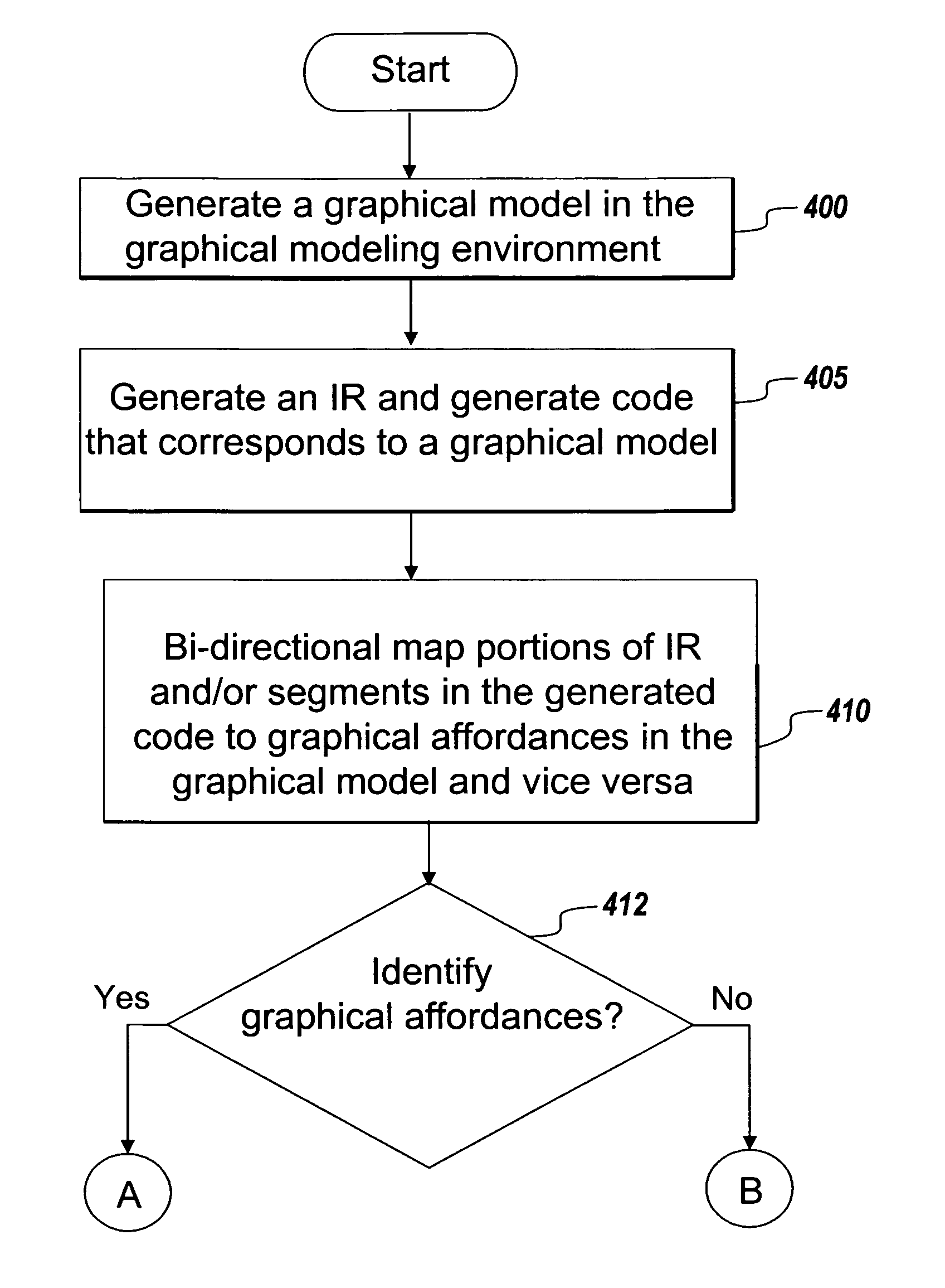
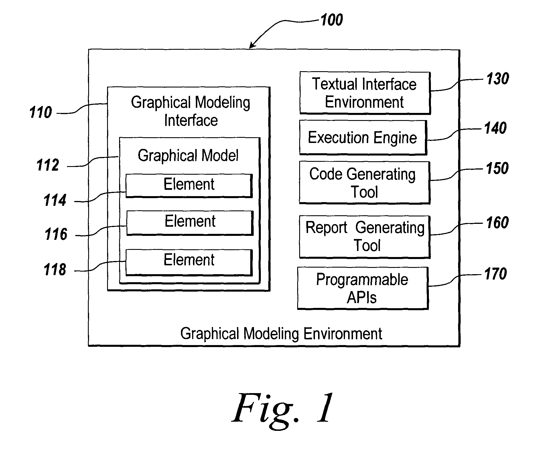
[0048]Exemplary embodiments described herein provide a graphical modeling environment to allow a user to generate a graphical model that maps to multiple entities. The entities may include a requirements document, generated code, an intermediate representation, a generated report, etc. These entities may also be mapped to one another.

[0049]The mapping between the entities may be bi-directional. For example, a graphical model can be mapped to generated code and vice versa. The bi-directional mapping may facilitate graphical identification of portions of the graphical model that correspond to selected segments of the generated code. The bi-directional mapping may also facilitate graphical identification of segments of generated code that correspond to selected portions of a graphical model. The parts of the entities that map to one another may use a one-to-one mapping, a one-to-many mapping, a many-to-one mapping, a many-to-many mapping, etc. The bi-directional mapping may be injectiv...


PUM


Abstract

Exemplary embodiments employ a mapping among entities that are related to each other. The entities may include a graphical model, generated code, a generated report, a requirements document and/or an intermediate representation. The mapping may facilitate graphical identifications between parts of one entity that maps to part of another entity. The graphical identification may occur based on a selection of a part in one of the entities.

Description

RELATED APPLICATIONS[0001]This application is a continuation-in-part, and claims priority to U.S. application Ser. No. 10 / 057,126, filed Oct. 25, 2001 and U.S. application Ser. No. 10 / 637,433, filed Aug. 7, 2003. This application also claims the benefit of, said Applications for all subject matter in common with this application. The disclosures of said Applications are hereby incorporated by reference in their entirety.BACKGROUND[0002]Graphical modeling environments, such as Simulink® software from The MathWorks, Inc. of Natick, Mass., cater to various aspects of dynamic system simulation, analysis and design. Such products allow users to perform numerous types of tasks including constructing system block diagram models. These graphical modeling environments may also be used to augment a predefined set of blocks with custom user-specified blocks, to compute and trace the temporal evolution of the dynamic system (“executing” the block diagram), to produce deployable software systems...

Claims


Application Information

Patent Timeline
IPC IPC(8): G06F9/44G06F17/22
CPCG06F8/10G06F8/34G06F8/35G06F8/73G06F11/3664G06F11/3688G06F11/3696G06F17/2241G06F17/2264G06F8/355G06F40/137G06F40/151
Inventor LIN, XIAOCANGPILLARISETTI, ARAVINDALDRICH, WILLIAM J.TUSCHNER, KAI
Owner THE MATHWORKS INC
Why Eureka
Try Eureka