Frame assembly mountable to an object

a frame and object technology, applied in the field of frame assemblies, can solve problems such as inaccessibility, and achieve the effect of pleasing appearan

Active Publication Date: 2012-01-31
SCHYMURA MARGARETE
View PDF17 Cites 9 Cited by
  • Summary
  • Abstract
  • Description
  • Claims
  • Application Information

AI Technical Summary

Benefits of technology

[0007]It is an object of the invention to provide a picture frame assembly which can be readily mounted to an object, such as a tree, flower stem, a candle, a vase, a basket, a gift wrapping device, a container, a column, and furniture.
[0015]According to another embodiment designed for an object having a known diameter, such as a candle, a frame element can be provided with a curved frame plate having an aperture therein and a surrounding wall having an edge with a radius of curvature which is smaller than that of the frame plate. The edge is provided with retaining tabs which are deformed to bear against the rear surface of the backing plate, which is received within the surrounding wall. The backing plate can be formed to have a curvature similar to or be deformable to conform to the curvature of the frame plate. Thereby the backing plate can assure that a picture element will be held flush against the rear surface of the frame plate, together with an optional transparent sheet, giving a neat appearance.

Problems solved by technology

Picture frame assemblies which fit flush against a cylindrical object, in particular a picture frame assembly which can be readily adjusted to any desired radius of curvature, are not available.

Method used


Image

  • Frame assembly mountable to an object
  • Frame assembly mountable to an object
  • Frame assembly mountable to an object

Examples


first embodiment

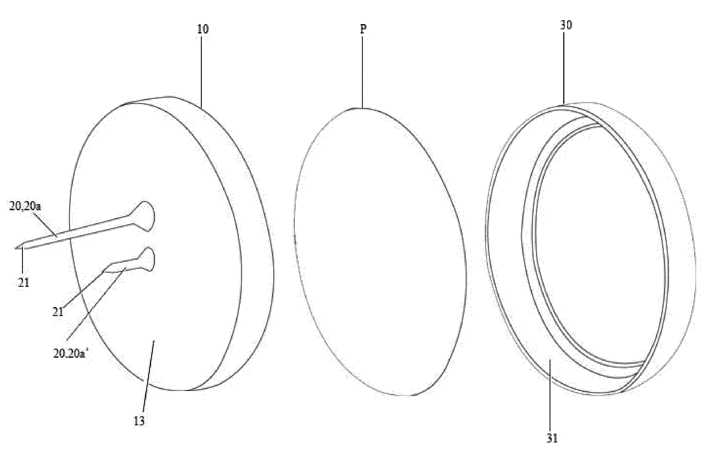
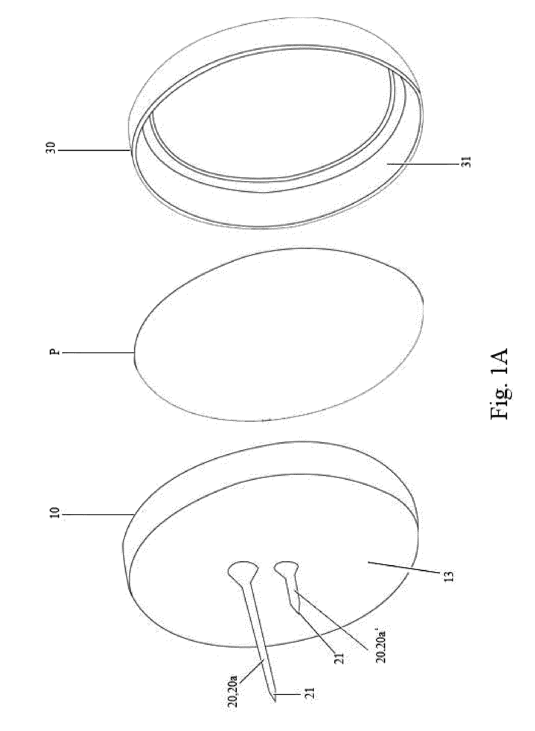
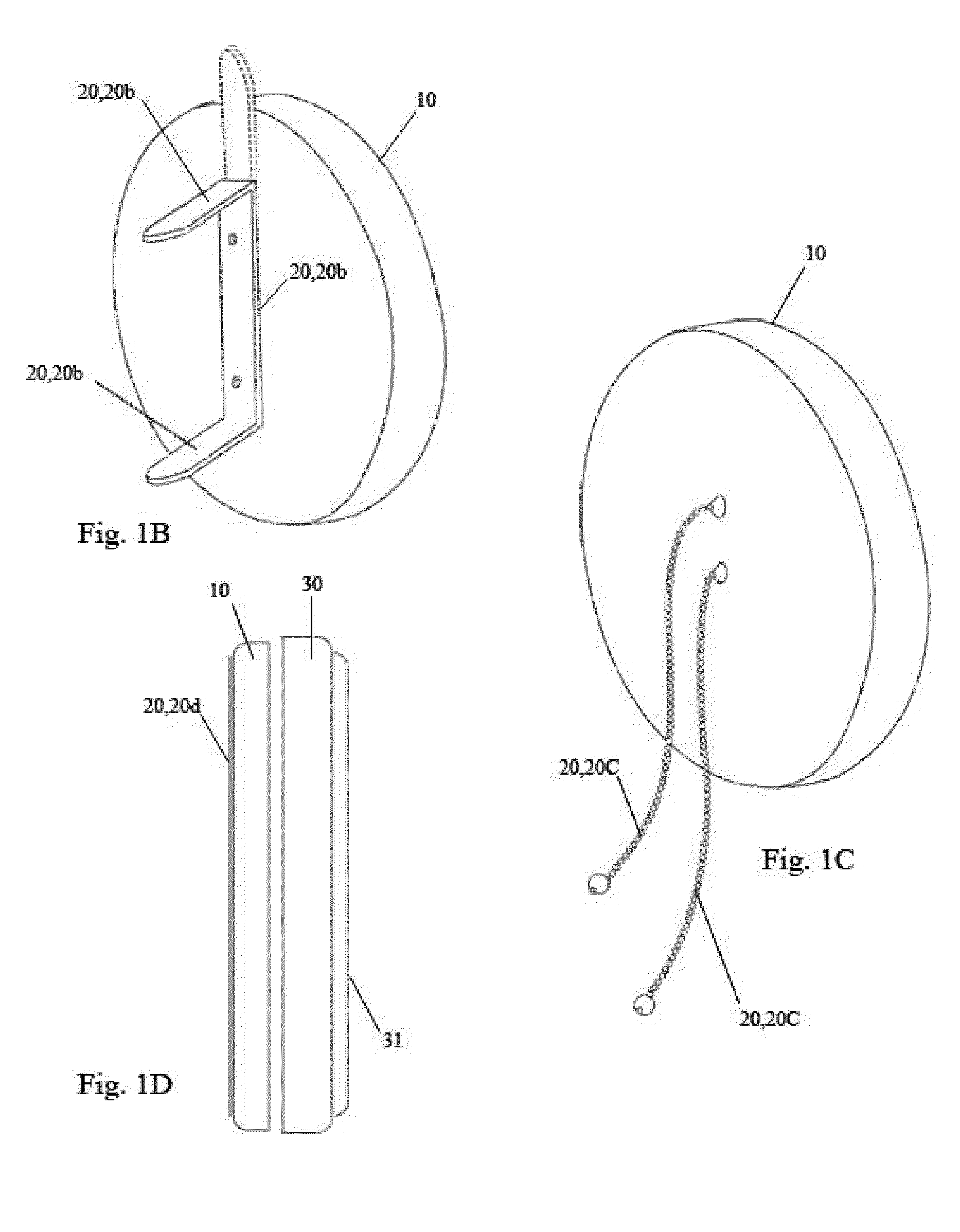
[0048]FIG. 1A shows a picture frame assembly having a backing plate 10 and a frame element 30 to hold a picture P element therebetween. In the example shown in FIG. 1A, the backing plate 10 can be received inside a surrounding wall 30a of the frame element 30 and retained therein by any of various conventional methods. For example, the backing plate 10 can be retained inside the surrounding wall 31 through friction engagement. The backing plate 10 and the frame element 30 can be configured in various forms. For example, the backing plate 10 can be either rigid or deformable. Additionally or alternatively, the frame element 30 can be a rigid or deformable member having a flat front surface 31, as is shown in FIG. 1D, or a curved front surface 31′ as is shown in FIG. 2D. The details of the backing plate 10 and the frame element 30 will be described in the following various embodiments.

[0049]The picture frame assembly includes one or more fastening elements 20 fixed to one of the backi...

second embodiment

[0054]FIGS. 2A to 2D illustrate a picture frame assembly formed according to a In this embodiment, the surrounding wall 30a of the frame element 30 is profiled to conform to a curved surface of the object, to which the picture frame assembly is to be mounted. For example, the height of the surrounding wall 30a reduces from the two opposite sides toward the top and bottom portions of the frame element 30. When the top and bottom portions of the frame element 30 are placed against an axial direction of a cylindrical surface, the surrounding wall 30a hugs the cylindrical surface in a circumferential direction, resulting in a smooth fitting between the frame assembly and the cylindrical object.

[0055]In the example shown in FIGS. 2B and 2C, the front surface 31 of the frame element 30 can be substantially flat. When the frame element 30 of FIGS. 2B and 2C is made of rigid material and thus not subject to bending, the backing plate can be also be rigid. In the example shown in FIG. 2D, t...

third embodiment

[0057]FIGS. 3A and 3B show a frame assembly, in which the frame element 50 includes a curved frame plate 52 having a front surface 53 and a rear surface 54 which receives a planar picture element visible through aperture 55, possibly with a protective transparent sheet. A surrounding wall 56 extends rearward from the periphery of the frame plate 52 to an edge 57 lying in a cylindrical plane having a radius of curvature which is smaller than that of the frame plate 52.

[0058]The backing plate 10 is received within the surrounding wall 56 and held against the frame plate 52 by plastically deformable retaining tabs 58 extending from the edge 57. As is discussed below, the retaining tabs 58 can also be separately formed and attached to the frame plate 52 by conventional fasteners such as nail elements. Additionally or alternatively, the retaining tabs 58 can be formed in various shapes such as a loop shape.

[0059]In one example, the frame element 50 is not intended to be deformed by a use...


PUM


Abstract

A picture frame assembly includes a backing plate having a front surface, a rear surface, and a plurality of parallel grooves in one of the surfaces. The material and thickness of the backing plate are chosen so that the backing plate can be plastically deformed about a bending axis parallel to the grooves. At least one frame element, which can be formed integrally with the backing plate, is for provided for retaining a planar picture element against the front surface of the backing plate. A fastener extends from the rear surface for mounting the assembly to any of various objects, such as a tree, flower stem, a candle, a vase, a basket, a gift wrapping device, a container, a column, and furniture.

Description

CROSS-REFERENCE TO RELATED APPLICATIONS[0001]This patent application is a continuation-in-part of U.S. patent application Ser. No. 10 / 580,897 filed Sep. 11, 2006 now U.S. Pat. No. 7,421,810 which is a U.S. national stage of International Patent Application No. PCT / US04 / 42503 filed Dec. 17, 2004 claiming priority to U.S. Provisional Patent Application No. 60 / 531,336 filed Dec. 19, 2003.BACKGROUND OF THE INVENTION[0002]1. Field of the Invention[0003]The invention relates generally to a frame assembly. In particular, the invention relates to a picture frame assembly of the type that can be readily mounted onto an object.[0004]2. Description of the Related Art[0005]Picture frame assemblies including a backing plate and a frame element for retaining a photograph or other planar picture element against the backing element are well known. Such frame assemblies include means for retaining the backing element in the frame, and can include a sheet of glass or other transparent material over t...

Claims


Application Information

Patent Timeline
Patent Type & Authority Patents(United States)
IPC IPC(8): A47G1/06
CPCA47G1/0616A47G1/22B44C5/02G09F23/00
Inventor SCHYMURA, MARGARETE
Owner SCHYMURA MARGARETE
Why Eureka
Try Eureka