Bone plate and bone plate assemblies including polyaxial fasteners

a technology of bone plate and polyaxial fasteners, which is applied in the field of orthopedic fixation devices and bone plate assemblies, can solve the problems of limiting their use, unidirectional locking screws, and shattered bone fragments,

Active Publication Date: 2012-01-31
SMITH & NEPHEW INC
View PDF460 Cites 128 Cited by
  • Summary
  • Abstract
  • Description
  • Claims
  • Application Information

AI Technical Summary

Benefits of technology

[0014]In certain embodiments there is a bone plate comprising a first opening. The first opening may be threaded, and the threads may be made of a first material. A first fastener may be inserted into the first opening in order to secure the bone plate to the bone. In certain embodiments the first fastener has a head at least partially made of a polymeric material that is softer than the first material of the threads of the first opening. In use, the first fastener is positioned and rotated in the first opening, and the threads of the first opening form “threads” into the polymeric material of the first fastener to thereby fix the orientation of the first fastener relative to the first opening. Thus, the first fastener may be secured at one of a plurality of possible angles within the first opening. This may help in capturing “renegade” or random bone fragments that have split from the bone during fracture, and may help in securing the bone fragments to the bone plate.

Problems solved by technology

However, although locking screws may reduce the incidence of loosening, they have limitations.
In short, locking screws are unidirectional, limiting their use in some instances.
For example, when treating a severe fracture, bone fragments may be shattered and in irregular positions.
Although a surgeon may wish to obtain the benefits of a locking screw and bone plate used together, the pre-determined angle at which the locking screw extends from the plate may not be the angle that would allow the surgeon to “grab” (or seize, or otherwise secure) the desired, random bone fragment.
Moreover, locking screws secured in a plate have a limited capability to compress bone fragments, since once the screw is fully rotated to lock with the plate, it can rotate no further to compress the plate to the bone.
Conversely, there may be situations where the screw rotates sufficiently to capture bone, but does not rotate sufficiently to lock to the plate.
In short, while locking screws were useful to provide rigid fixation, they often could not perform other functions typically performed by traditional non-locking or compression screws (also referred to as cortical or cancellous screws).
Although non-locking screws are secured into bone in the same way that locking screws are, they are not secured to the plate.
Thus, while not optimal in providing a rigid construct between the screw and plate, they can be inserted at various angles because they are not limited by the thread-to-thread contact of locking screws with the bone plate.
However, because these combination slots are only partially threaded, the locking screw(s) may not be able to maintain the fixed angular relationship between the screw(s) and plate under physiological loads.
This can result in loss of fixation or loss of established intra-operative plate orientation.
Moreover, the locking screw can still only be inserted at a single angle—the predetermined angle defined by the manufacturer.
Additionally, current bone plate and screw systems still limit a surgeon's ability to both (a) lock a fastener with respect to the bone plate, but still (b) allow the fastener to extend from the bone plate at various angles.
Locking screws lock into the plate, but only in a single angular configuration, and non-locking screws allow various angle configurations, but they do not provide a stable construct with the plate.
Accordingly, none of these options allow a surgeon to capture bone fragments that do not fall in line with the axis of the opening provided on the plate in a rigid fashion.
Thus, currently available options can still lead to mal-alignment and poor clinical results.
Such a system can be cumbersome to use because, although the multidirectional peg can be inserted at any angle, the surgeon then needs to thread a small cap onto the top of the peg head and into the plate, requiring an extra step, extra time, and extra instrumentation.
Such systems also fail to allow the use of non-locking members in conjunction with the locking and multidirectional pegs.
There are challenges with such systems, however.
First, the deformable inserts cannot be used with non-locking screws.
Second, the deformable inserts do not have the strength to receive and hold a regular locking screw.
Thus, the unavailability of non-locking screws and regular locking screws do not provide the surgeon with options.
Finally, plates with deformable inserts are more expensive to manufacture than regular bone plates.

Method used


Image

  • Bone plate and bone plate assemblies including polyaxial fasteners
  • Bone plate and bone plate assemblies including polyaxial fasteners
  • Bone plate and bone plate assemblies including polyaxial fasteners

Examples


Embodiment Construction

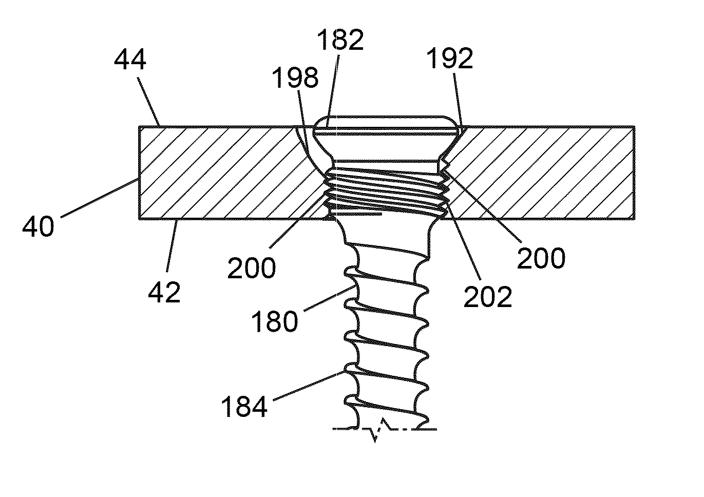
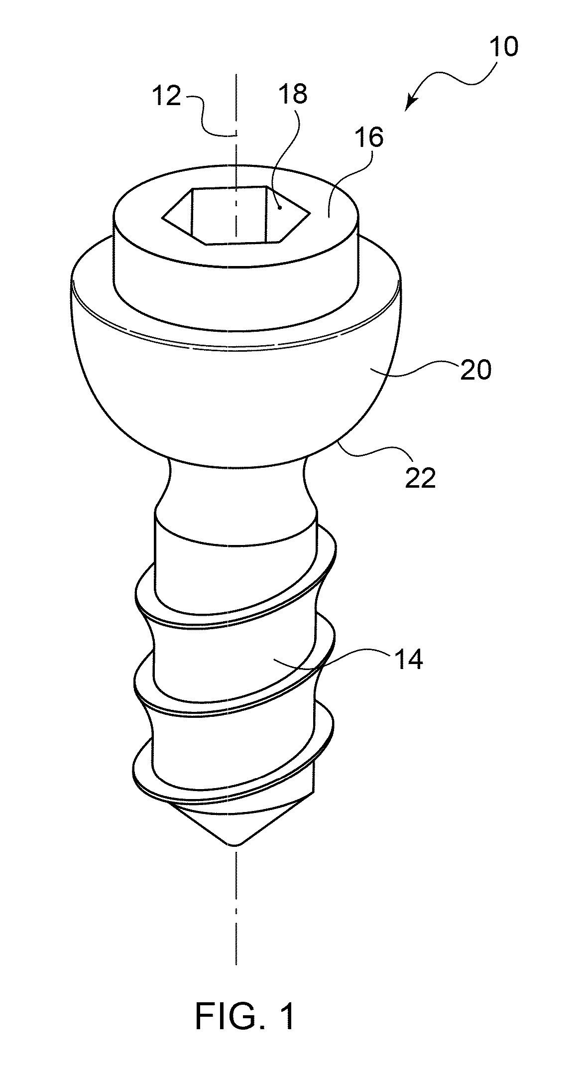
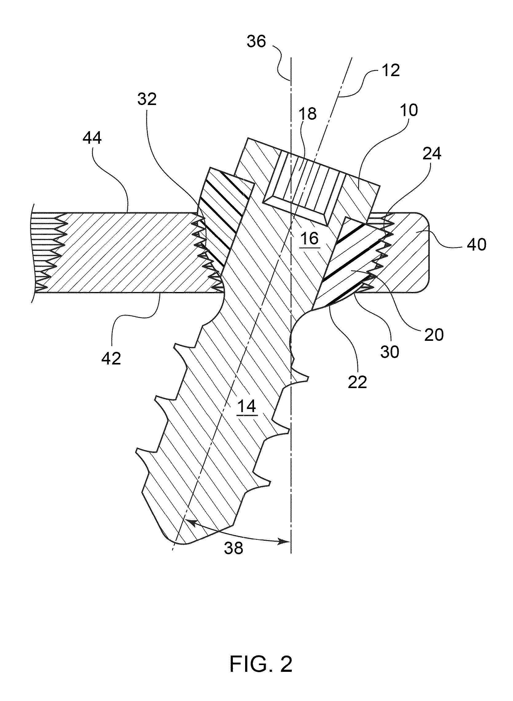
[0056]Embodiments of the present invention provide a fastener 10 for polyaxial fixation in a variety of different types of bone plate openings. FIGS. 1 and 2 illustrate an embodiment of one such fastener. This application uses the terms “fastener” and “screw” interchangeably. Fastener 10 includes a head 16 and a shaft 14 that defines a fastener central axis 12. In FIGS. 1 and 2, the shaft 14 is threaded. The shaft 14 may be fully threaded, partially threaded, comprise a helical blade, and / or may comprise one or more tacks, deployable talons, expandable elements, or so forth. Any feature that allows shaft 14 to engage bone is considered within the scope of this invention and may be referred to generally as a “threaded shaft” for the sake of convenience. It is also possible that shaft 14 is not threaded, so that fastener 10 takes the form of a peg or a pin. This alternative embodiment may be preferred in certain procedures where, for instance, the main goal is to prevent tilting of a ...


PUM


Abstract

A system for fixation of bone, including a bone plate with an opening comprising threads made of a first material and a fastener with a head at least partially comprising a polymeric material that is softer than the first material. In some embodiments, when the fastener is inserted into the first opening, the threads of the first opening form threads in the polymeric material on the head of the fastener and secure the fastener in place at one of a plurality of possible angles within the first opening. The first opening additionally accepts a fastener with a substantially spherical head for compression of a fracture, or a fastener with a threaded head that engages with the threads of the threaded opening. In some embodiments the first opening includes a substantially frustoconical-shaped top portion. In other embodiments there may be a second opening that is either non-threaded or comprises a plurality of protruding fins.

Description

CROSS REFERENCE TO RELATED APPLICATIONS[0001]This application is a continuation-in-part of U.S. Application Ser. No. 11 / 996,795 filed Jan. 25, 2008 and entitled “Polyaxial Plate,” which is a national phase application of PCT Application Serial No. PCT / US2006 / 028778 filed Jul. 25, 2006 and entitled “Systems and Methods for Using Polyaxial Plates,” which claims the benefit of U.S. Provisional Application Ser. No. 60 / 702,231, filed Jul. 25, 2005 and entitled “Locking Screw,” and this application is also a continuation-in-part of U.S. application Ser. No. 11 / 644,306, filed Dec. 22, 2006 and entitled “Bone Plates and Bone Plate Assemblies,” now U.S. Pat. No. 7,905,910, which is a continuation of U.S. application Ser. No. 10 / 673,833, filed Sep. 29, 2003 and entitled “Bone Plates and Bone Plate Assemblies,” now U.S. Pat. No. 7,179,260, the entire contents of prior applications are hereby incorporated by reference.FIELD OF THE INVENTION[0002]The present invention relates generally to orthop...

Claims


Application Information

Patent Timeline
Patent Type & Authority Patents(United States)
IPC IPC(8): A61B17/80A61B17/86
CPCA61B17/8014A61B17/8057A61B17/8061A61B17/8085A61B17/8605
Inventor AUSTIN, GENE EDWARDBLACK, BRIAN L.JANNA, SIED W.PETTEYS, TIMOTHY J.RAINS, JAMES K.SCHNEIDER, JOHN B.HARMON, JON A.GERLACH, DARIN S.JAMES, ANTHONY H.
Owner SMITH & NEPHEW INC
Why Eureka
Try Eureka