Controlling vehicle dynamics through the use of an image sensor system

a technology of image sensor and vehicle dynamics, applied in the direction of image enhancement, suspension, instruments, etc., can solve problems such as recognizing dangers, and achieve the effects of reducing the cost of such systems, and reducing the cost per function

Active Publication Date: 2012-01-31
ROBERT BOSCH GMBH
View PDF18 Cites 17 Cited by
  • Summary
  • Abstract
  • Description
  • Claims
  • Application Information

AI Technical Summary

Benefits of technology

[0003]An example method and device, as described below, for controlling driving dynamics in a motor vehicle may have at least one image sensor system, at least two image sensors being provided which record generally the same scene. The example method and device may have the advantage that the image sensor systems provided in motor vehicles are used for other functions. Stereo cameras are particularly advantageous. Image sensors systems and stereo cameras may be used, for example, as part of an automatic speed control and / or distance control, for example in the adaptive cruise control (ACC) system in a motor vehicle. Other possible applications of exterior video camera systems are, for example: precrash sensing, pedestrian detection, rollover detection. When the same image sensor system is used for a plurality of functions, the costs for such systems are reduced, because the costs per function are lowered. It is particularly advantageous to link the image sensor system and / or the stereo camera to a sensor platform, where various sensors are connected to a data bus and are used synergetically by various control units. This further reduces the costs per function. Thus, a broad application of the described functions is made possible in motor vehicles. In particular, a broad application of driving dynamics control in motor vehicles located in the highway space enhances traffic safety as a whole.
[0004]It may be advantageous if at least one measured value is determined from the generated image information, the measured value being used for vehicle dynamics control. By defining the at least one measured value, a simple linking of the image sensor system to the vehicle dynamics control is made possible, since a defined measured value is available for the vehicle dynamics control. This enables an image sensor system to be simply adapted to the vehicle dynamics control, since the specific properties of the image sensor system, such as spatial resolution and / or gray-scale resolution and / or color resolution and / or sampling frequency, do not enter into the vehicle dynamics control.
[0005]Defining at least one fixed image point and subsequently determining the image coordinates of the image point in at least two images of one image sequence advantageously leads to a rapid and fault-tolerant determination of at least one measured value for controlling vehicle dynamics from the generated image information of the image sensor system.

Problems solved by technology

By determining the pitch acceleration and / or the pitch velocity and / or the pitch angle, dangers may be recognized which arise from an excessive pitching motion of the motor vehicle.

Method used


Image

  • Controlling vehicle dynamics through the use of an image sensor system
  • Controlling vehicle dynamics through the use of an image sensor system
  • Controlling vehicle dynamics through the use of an image sensor system

Examples


Embodiment Construction

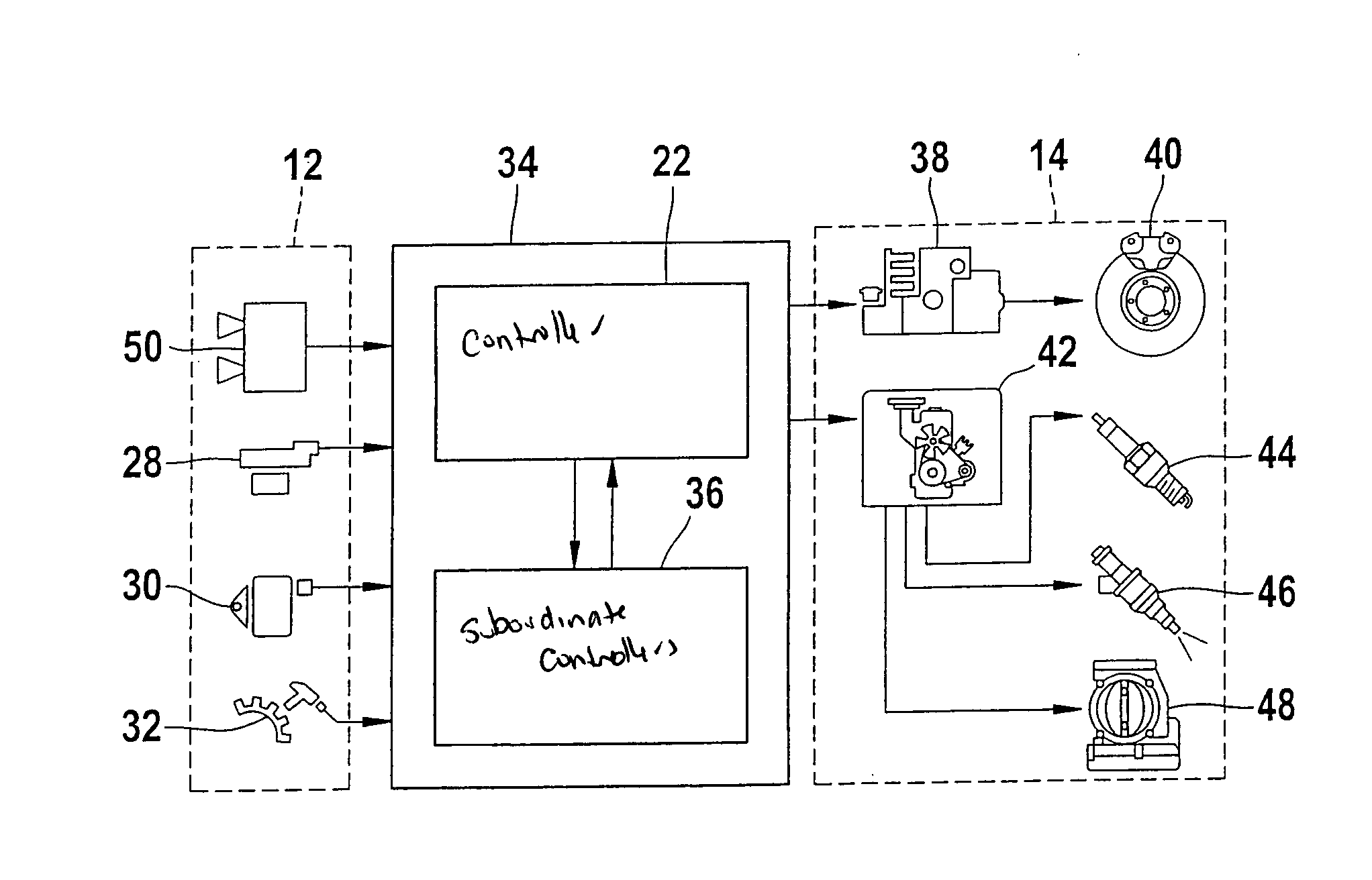
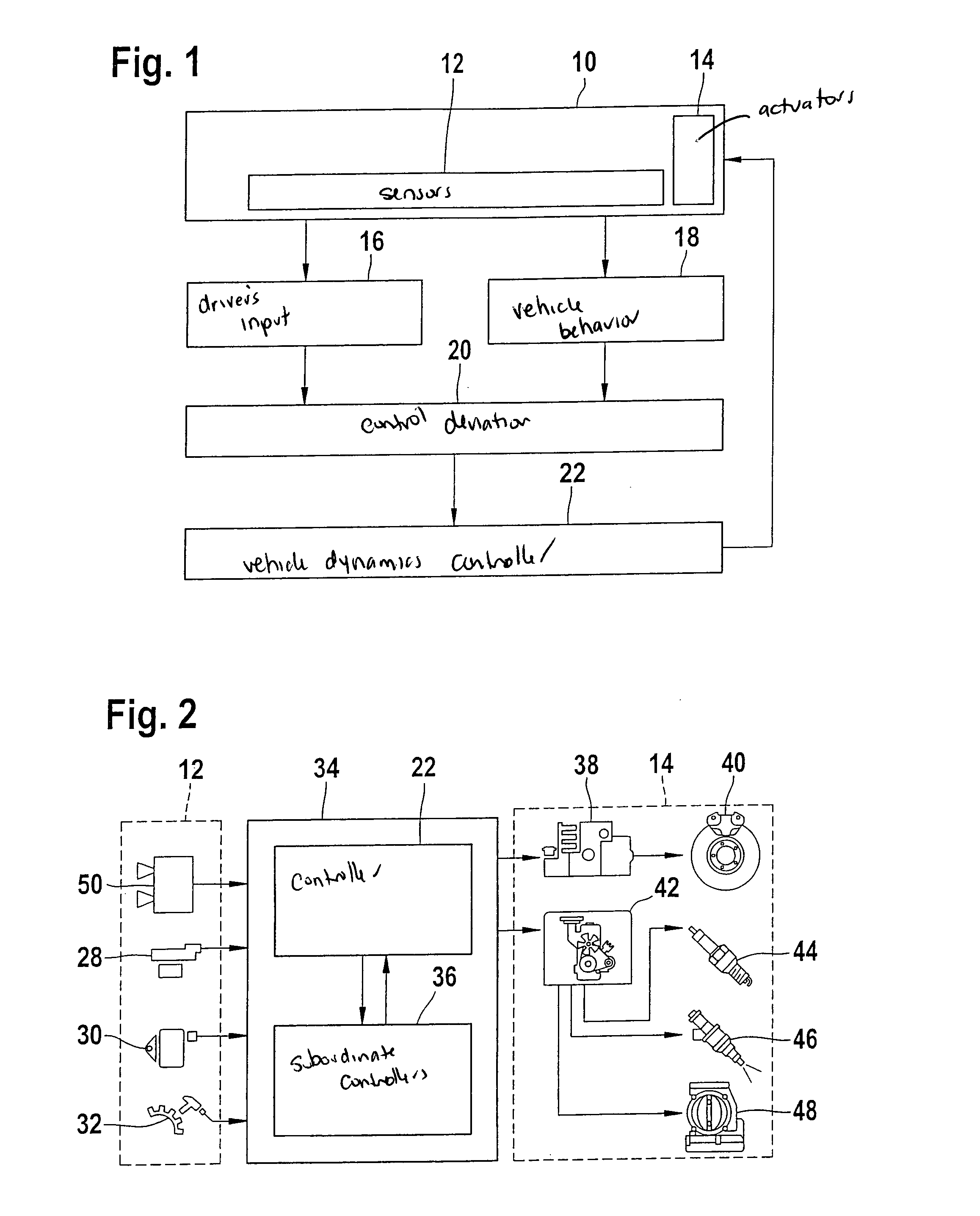
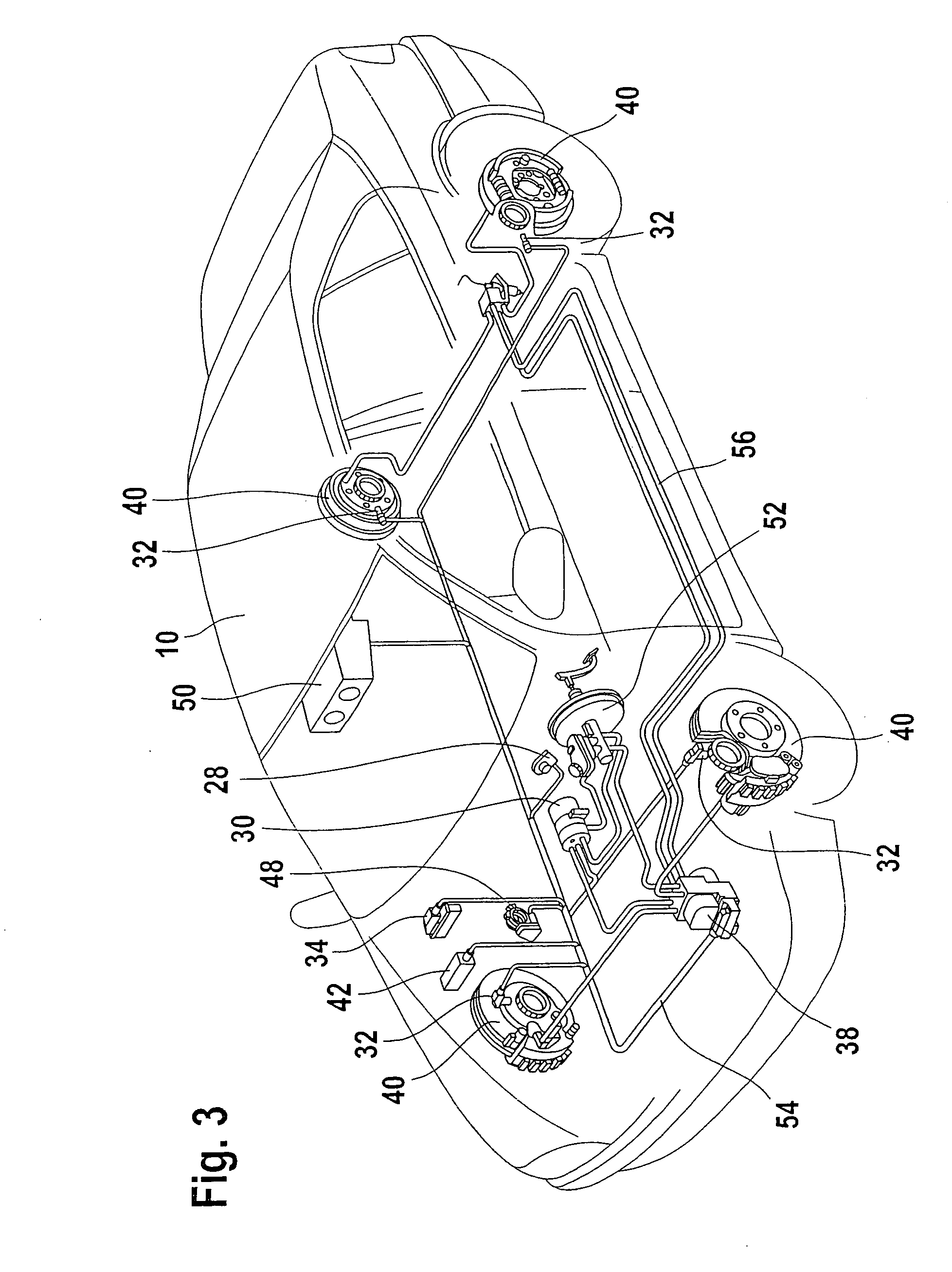
[0023]FIG. 1 shows a block diagram of the vehicle dynamics control in a motor vehicle 10 in a preferred exemplary embodiment, including sensors 12, actuators (control elements) 14, driver's input (nominal behavior) 16, vehicle behavior (actual behavior) 18, control deviation 20, and vehicle dynamics controller 22. It is the aim of the vehicle dynamics control to keep motor vehicle 10 stable and in the lane. Driver's input 16 is ascertained by sensors 12 situated in motor vehicle 10. Vehicle behavior 18 is determined in parallel by sensors 12. Control deviation 20 is calculated from driver's input 16 and vehicle behavior 18. Control deviation 20 is used as the input variable for driving dynamics controller 22. Driving dynamics controller 22 controls the actuators (control elements) 14 with the objective of minimizing control deviation 20. As actuators 14, the wheel brakes and / or the engine of motor vehicle 10 are used in particular. By adjusting the braking and tractive forces at the...


PUM


Abstract

A method for controlling vehicle dynamics in a motor vehicle, at least one sensor recording at least one measured value; at least one actuator for controlling vehicle dynamics being driven as a function of the at least one measured value; at least one image sensor system generating image information from the motor-vehicle surround for controlling vehicle dynamics; at least two image sensors being provided which essentially record the same scene.

Description

FIELD OF THE INVENTION[0001]The present invention relates to a method and a device for controlling vehicle dynamics in a motor vehicle using at least one image sensor system composed of at least two image sensors which record basically the same scene.BACKGROUND INFORMATION[0002]Devices and methods for controlling vehicle dynamics in a motor vehicle are generally known. For example, a device and a method for controlling driving dynamics in a motor vehicle are described in Zanten, Erhardt, Pfaff: “VDC, The Vehicle Dynamics Control System of Bosch”, Individual Conference Report, lecture: International Congress and Exposition, Feb. 27-Mar. 2, 1995, Detroit, Mich., SAE Paper 950759, 1995. Vehicle dynamics control is a system for keeping a motor vehicle stable and in the lane. This is achieved by selectively braking individual wheels of the motor vehicle. To this end, sensors are used to determine the driver's input, thus the nominal behavior of the motor vehicle, and the vehicle behavior...

Claims


Application Information

Patent Timeline
Patent Type & Authority Patents(United States)
IPC IPC(8): G06F7/14B60Q1/00G06F17/00G06F19/00B60Q9/00B60T8/172B60T8/1755G01S5/16H04N13/00
CPCB60T8/172B60T8/17551G06T7/73G01S5/16G06T2207/10012G06T2207/30244
Inventor MATTES, BERNHARDHERRMANN, THOMAS
Owner ROBERT BOSCH GMBH
Why Eureka
Try Eureka