High-pressure/high temperature packer seal

a packer and high temperature technology, applied in the direction of sealing/packing, fluid removal, borehole/well accessories, etc., can solve the problems of large volume of elastomer, difficult or impossible mold compression set packer elements from certain specialized elastomers, and the elastomeric seal element may become too soft to properly deploy, etc., to achieve high resistance to degradation and reliable

Active Publication Date: 2012-02-07
BAKER HUGHES HLDG LLC
View PDF52 Cites 90 Cited by
  • Summary
  • Abstract
  • Description
  • Claims
  • Application Information

AI Technical Summary

Benefits of technology

[0006]The devices and methods of the present invention provide a packer design that overcomes a number of the problems of the prior art. A packer design in accordance with the present invention provides a reliable fluid seal which is highly resistant to degradation from high temperatures and pressures. In a preferred embodiment, a packer device is described which includes an elastomeric packer element which is seated upon an inner sleeve that surrounds a central inner mandrel. The inner sleeve and the inner mandrel are oriented at an angle of departure with respect to the central axis of the tool, thereby providing a ramp assembly which helps to set the packer device. An anchor ring and a retaining ring are located on opposite axial sides of the packer element. The retaining ring is secured to the sleeve, while the anchor ring is axially moveable with respect to the sleeve.

Problems solved by technology

Both of these designs are problematic when used at extreme wellbore depths wherein there are very high pressures and temperatures which tend to degrade elastomers.
Compression set packers inherently require large volumes of elastomer, which is very expensive.
In addition, it may be difficult or impossible to mold compression set packer elements from certain specialized elastomers that are resistant to high temperatures and pressures.
Also at high pressures, the elastomeric seal element may become too soft to properly deploy anti-extrusion devices which prevent the elastomer from bleeding out along the axial space between the packer and the surrounding tubing.
But it is currently not feasible to bond elastomers that are greatly resistant to high temperatures and pressures to such inserts.
Ramp set seals also have a tendency to leak when pressure is applied to the side with the smaller cross-section because the pressure pushes the seal element down the ramp.
Even when a ratchet mechanism is used to try to retain the seal element on the ramp, there is still some inherent slippage that occurs.

Method used


Image

  • High-pressure/high temperature packer seal
  • High-pressure/high temperature packer seal
  • High-pressure/high temperature packer seal

Examples


Embodiment Construction

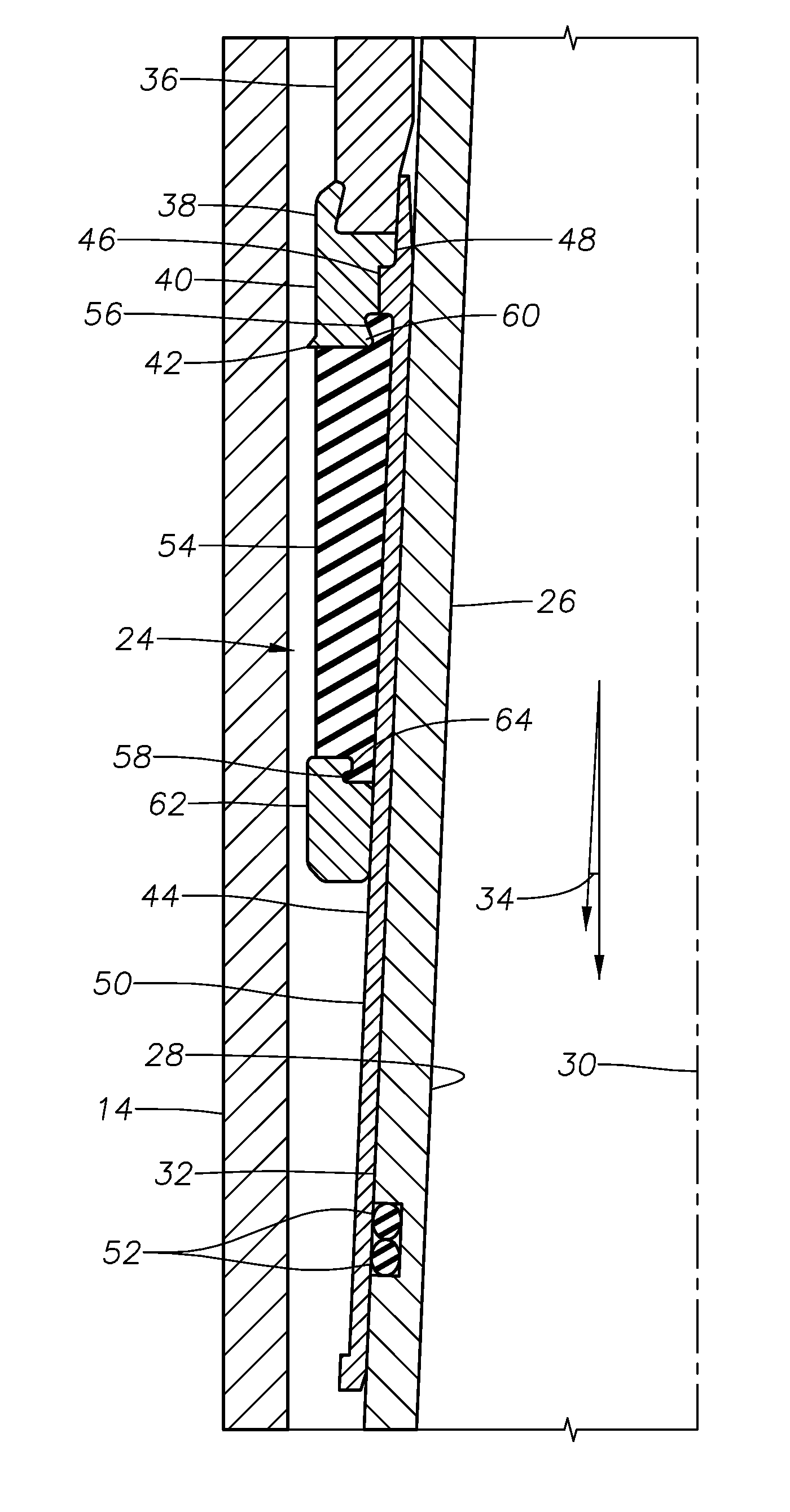
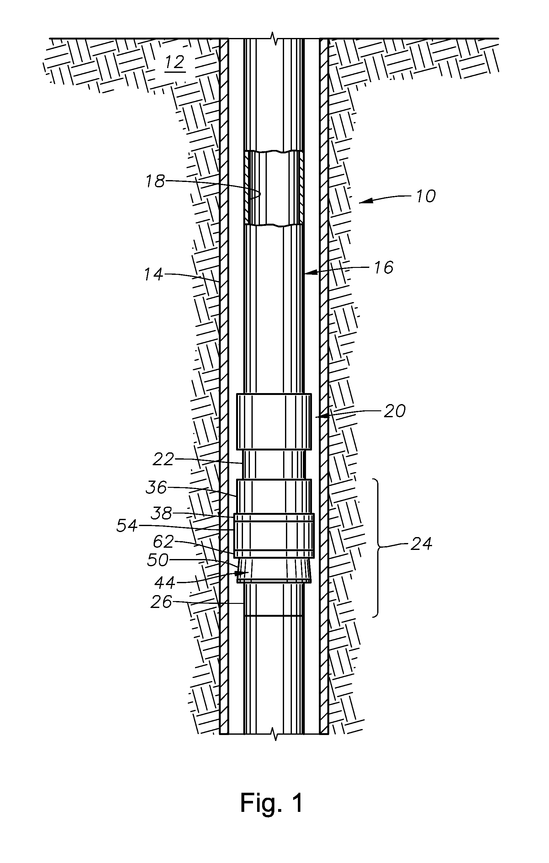
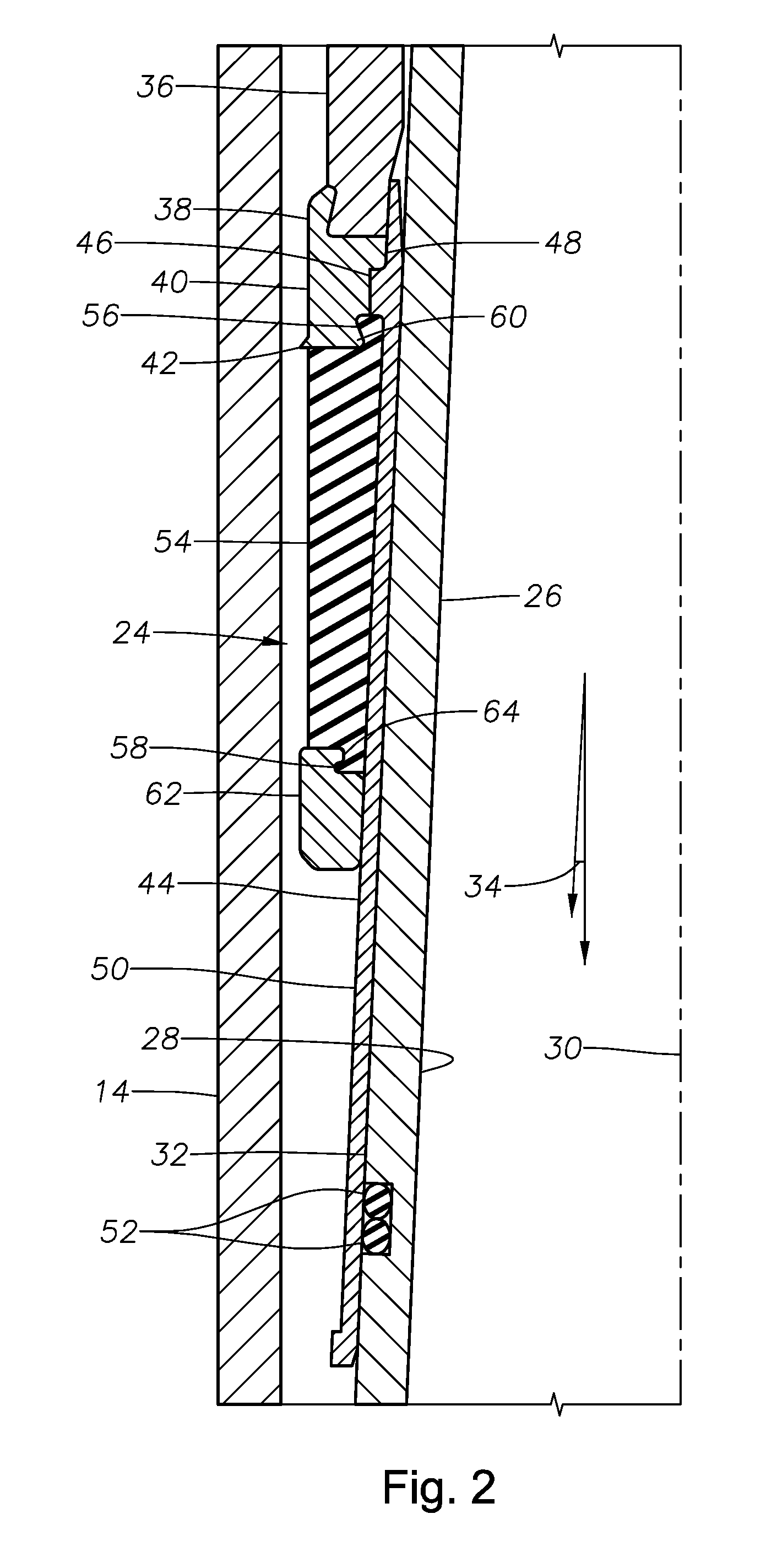
[0018]FIG. 1 illustrates an exemplary hydrocarbon production wellbore 10 that has been drilled through the earth 12 and has been lined with casing 14. A production tubing string 16 is disposed within the casing 14, having been run in from the surface (not shown) in a manner known in the art. A central flowbore 18 is defined along the length of the production tubing string 16. The production tubing string 16 may be formed of a number of interconnected production tubing sections, or it may be formed of coiled tubing. A packer setting tool 20 is incorporated into the production tubing string 16. The setting tool 20 operates to set a packer by axial movement of a setting sleeve 22. The setting tool 20 may be actuated electrically, hydraulically, or in other ways known in the art. Two commercially available setting tools which would be suitable for use as the setting tool 20 are the Baker Hughes Model “E-4” Wireline Setting Tool and the “BH” Hydraulic Setting Tool, both of which are avai...


PUM


Abstract

A packer device includes an elastomeric packer element which is seated upon an inner sleeve that surrounds a central inner mandrel. The inner sleeve and the inner mandrel are oriented at an angle of departure with respect to the central axis of the tool, thereby providing a ramp assembly which helps to set the packer device. An anchor ring and a retaining ring are located on opposite axial sides of the packer element and contact the surrounding tubular member.

Description

BACKGROUND OF THE INVENTION[0001]1. Field of the Invention[0002]The present invention generally relates to packer and sealing devices of the type used within a wellbore.[0003]2. Description of the Related Art[0004]There are generally two separate categories of designs for elastomeric wellbore packer seals: those that are set by axial compression and those that are set by moving the seal element radially outwardly with a ramp. Both of these designs are problematic when used at extreme wellbore depths wherein there are very high pressures and temperatures which tend to degrade elastomers. A compression set packer seal is compressed axially, which causes the seal element to expand radially until it contacts and seals against the inner radial surface of the surrounding casing or other tubular member. Compression set packers inherently require large volumes of elastomer, which is very expensive. In addition, it may be difficult or impossible to mold compression set packer elements from c...

Claims


Application Information

Patent Timeline
Patent Type & Authority Patents(United States)
IPC IPC(8): E21B33/129E21B23/01
CPCE21B33/1216E21B33/128E21B23/06
Inventor DOANE, JAMES C.ROBINSON, SAMUEL I.
Owner BAKER HUGHES HLDG LLC
Why Eureka
Try Eureka