Guiding wheel assembly, especially for a hospital bed

a technology for guiding wheels and hospital beds, applied in the field of guiding wheel assemblies, can solve the problems of difficult to keep straight, high control force, noise,

Inactive Publication Date: 2012-02-07
LINET SPOL
View PDF34 Cites 38 Cited by
  • Summary
  • Abstract
  • Description
  • Claims
  • Application Information

AI Technical Summary

Benefits of technology

[0011]An advantage of this solution is that the guiding wheel is locked or unlocked immediately while the control forces are kept to the minimum. In addition, such a guiding wheel can be easily equipped with an electric drive as thanks to the design structure the power supply is simple.
[0015]For easy handling the pressing element may be equipped with a control pedal.

Problems solved by technology

Such a design makes it possible to move the bed easily in all directions, but during the movements along hospital corridors it is difficult to keep the straight direction.
A disadvantage of structures with separate control where the wheel is lowered onto the floor in such a way that the control force must overcome the force of the pressing spring is that the control force is relatively high while the accumulated energy of the compressed spring causes impacts during the control as well as noise when the wheel hits the floor.
A disadvantage in this case is delayed locking as the wheel is not locked in the straight direction until the corresponding parts of the locking mechanism are turned towards each other.
A disadvantage is that if it is necessary to move the bed in another than straight direction, you must exert an increased pressure on the bed to make the spring-loaded ball get out of the groove to deactivate the locking of the guiding wheel while the straight direction is locked again when during the turning of the wheel around the vertical axis the ball gets to the groove again.
This is also related to the risk of spontaneous unlocking of the guiding wheel when passing through a bed due to an excessive side force.
However, this solution requires higher skills of the personnel with regard to moving the bed and at the same time larger handling areas for turning (wider corridors) since the free end of the bed gets considerably out of direction.

Method used


Image

  • Guiding wheel assembly, especially for a hospital bed
  • Guiding wheel assembly, especially for a hospital bed
  • Guiding wheel assembly, especially for a hospital bed

Examples


Embodiment Construction

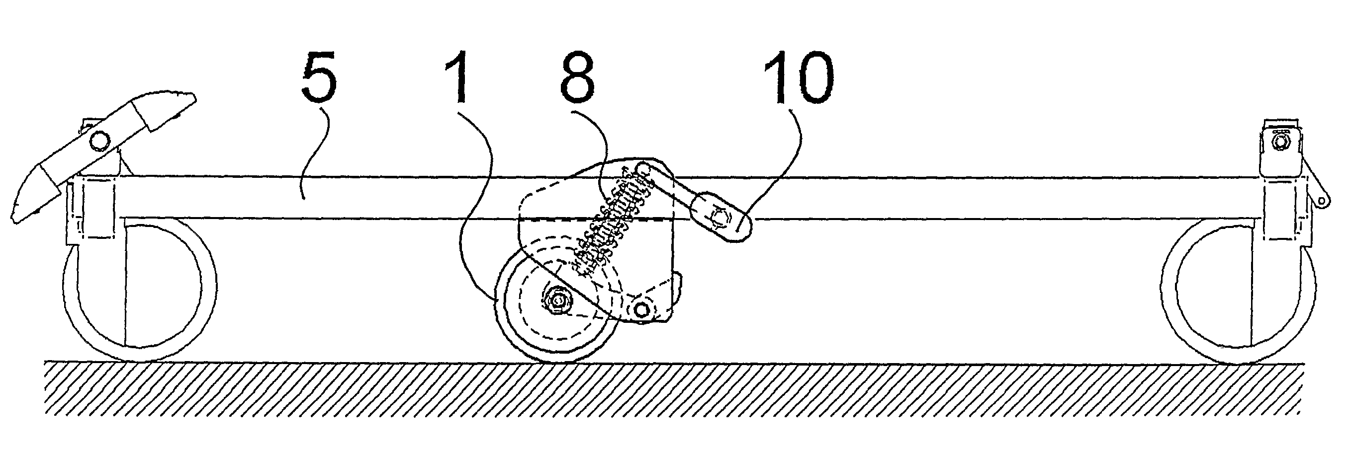
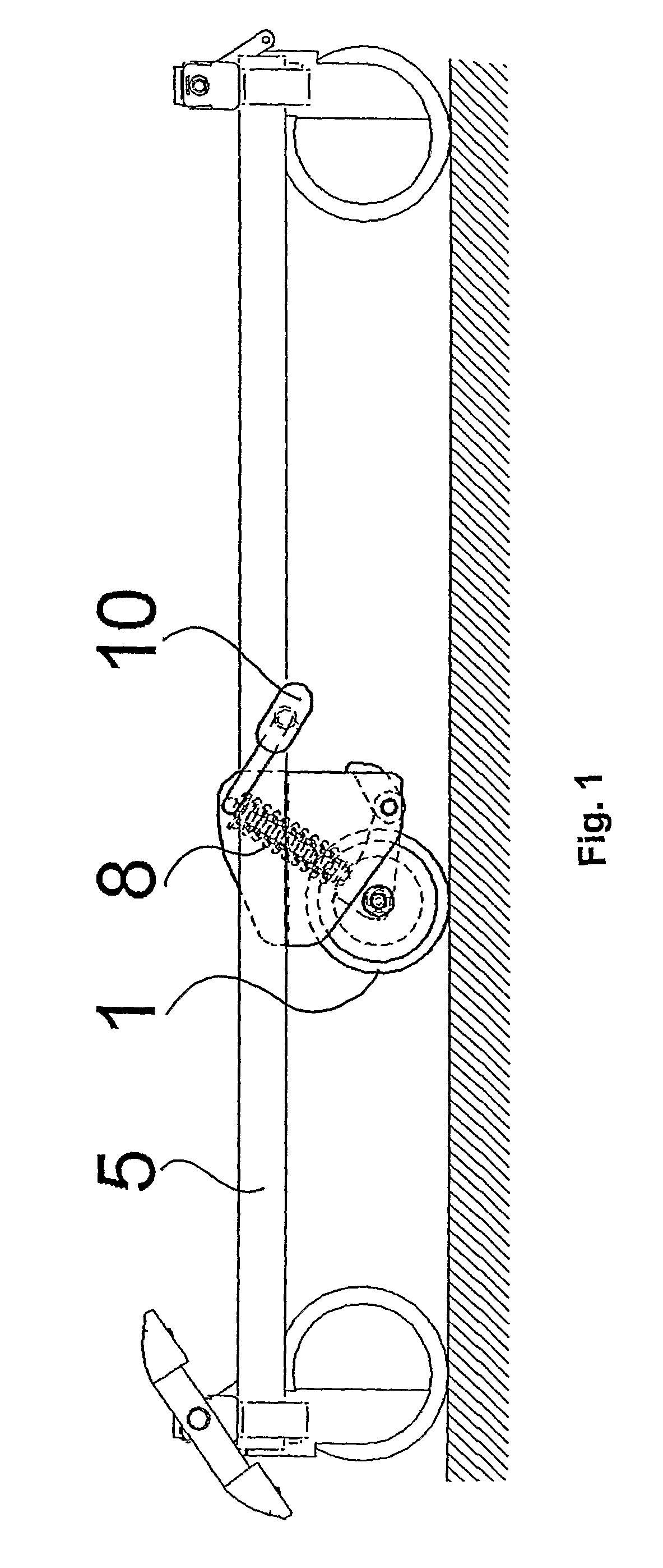
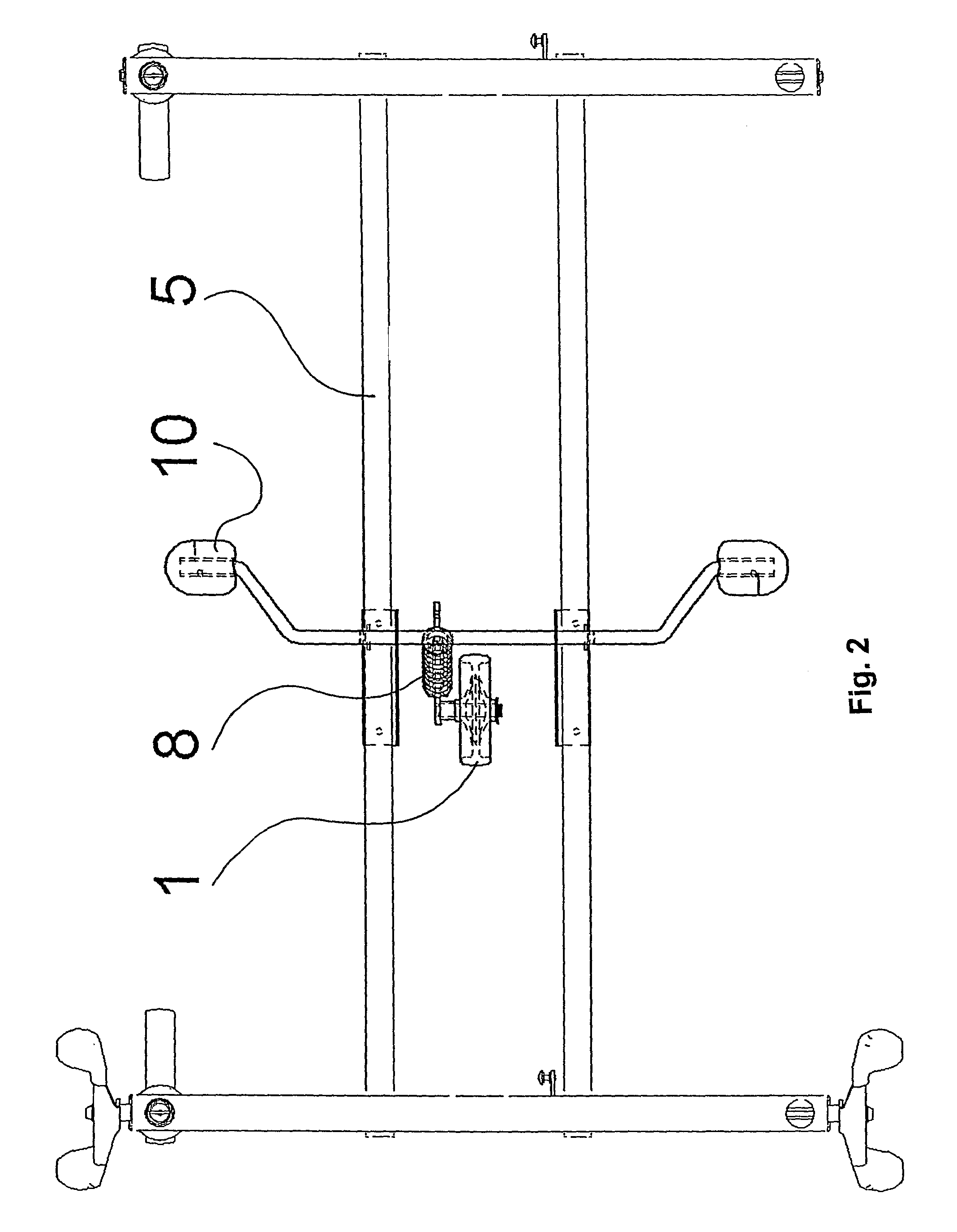
[0024]FIGS. 1 to 4 show a frame 5 of a hospital bed that has four traveling wheels in the corners that can freely turn around the vertical and horizontal axis. In the middle of the frame 5 there is the fifth, so called guiding wheel 1. The assembly of the guiding wheel 1 (see FIGS. 5 to 7) comprises side supporting metal sheets that are firmly fixed to the frame 5. The horizontal rotation axle 6 of the guiding wheel 1 is installed on an arm 7 that is fixed between the supporting side metal sheets of the frame 5 with the use of the axle 4. The arm can swing in the vertical plane about this axle 4, which is a first axle, with the axle 6 being a second axle about which the wheel rotates.

[0025]On the upper side of the arm 7 a track 3 is provided that the pressing element 8 presses on. As shown in FIGS. 5, 6 and 7, the pressing element 8 comprises a wound spring 11, and a pin 9 which may include a first inner part 12, and a second outer part 13 positioned around the first inner part 12 a...


PUM


Abstract

A guiding wheel assembly, mainly for a hospital bed, including a wheel (1) with a horizontal rotation axis (6) installed on an arm (7) that is fixed to the frame (5) with the use of an axis (4) allowing swinging in the vertical plane. The wheel (1) is firmly fixed in the straight direction. The arm (7) is provided with a track (3), against which a pressing element (8) leans. The pressing element (8) is fixed with a pin (9) to the frame (5) in a swinging way.

Description

[0001]This is a national stage application under 35 U.S.C. §371 of International Application[0002]PCT / CZ2007 / 000089 filed 25 Sep. 2007 and published in English, claiming the benefit of Czech Republic application PUV2006-18253 filed 9 Nov. 2006, the entire disclosures of which are incorporated herein by reference.TECHNICAL FIELD[0003]The invention relates to a guiding wheel assembly, mainly for a hospital bed, comprising a wheel with a horizontal rotation axis installed on an arm that is fixed to the frame with the use of an axis allowing swinging in the vertical plane.BACKGROUND ART[0004]Some hospital beds are equipped with wheels to enable transport of patients between individual workplaces of the hospital. In the corners of the bottom frame of such a bed there are four travelling wheels that are freely turning around the vertical and horizontal axis. Such a design makes it possible to move the bed easily in all directions, but during the movements along hospital corridors it is di...

Claims


Application Information

Patent Timeline
Patent Type & Authority Patents(United States)
IPC IPC(8): B60B33/04B60B33/06
CPCA61G7/08B60B33/0023B60B33/0039B60B33/0049B60B33/0063B60B33/066Y10T16/1943
Inventor SALUS, MICHAL
Owner LINET SPOL
Why Eureka
Try Eureka