Load stop for supporting a load on a load carrier

a technology for supporting a load and a load carrier, applied in the field of load stops, can solve the problems of time-consuming for craftsmen and other workers, and the load stop often becomes an obstruction

Active Publication Date: 2012-02-14
THULE SWEDEN AB
View PDF13 Cites 14 Cited by
  • Summary
  • Abstract
  • Description
  • Claims
  • Application Information

AI Technical Summary

Benefits of technology

[0005]A purpose of the present invention is to achieve a load stop which can easily be placed in the right working position along a load carrying tube and be fixed in that position. An additional purpose is to achieve a load stop which can, in a simple way, be moved away and located in a transporting position.

Problems solved by technology

A problem with a load stop of this known type is that it must be located in the right position for the intended load.
The load stop often becomes an obstruction and must be dismantled before the roof rack can be utilized for other types of loads.
This can be time-consuming for the craftsman and other workers who alternatingly transport, for example ladders, pipes, building boards, battens and the like on the roof rack.

Method used


Image

  • Load stop for supporting a load on a load carrier
  • Load stop for supporting a load on a load carrier
  • Load stop for supporting a load on a load carrier

Examples


Embodiment Construction

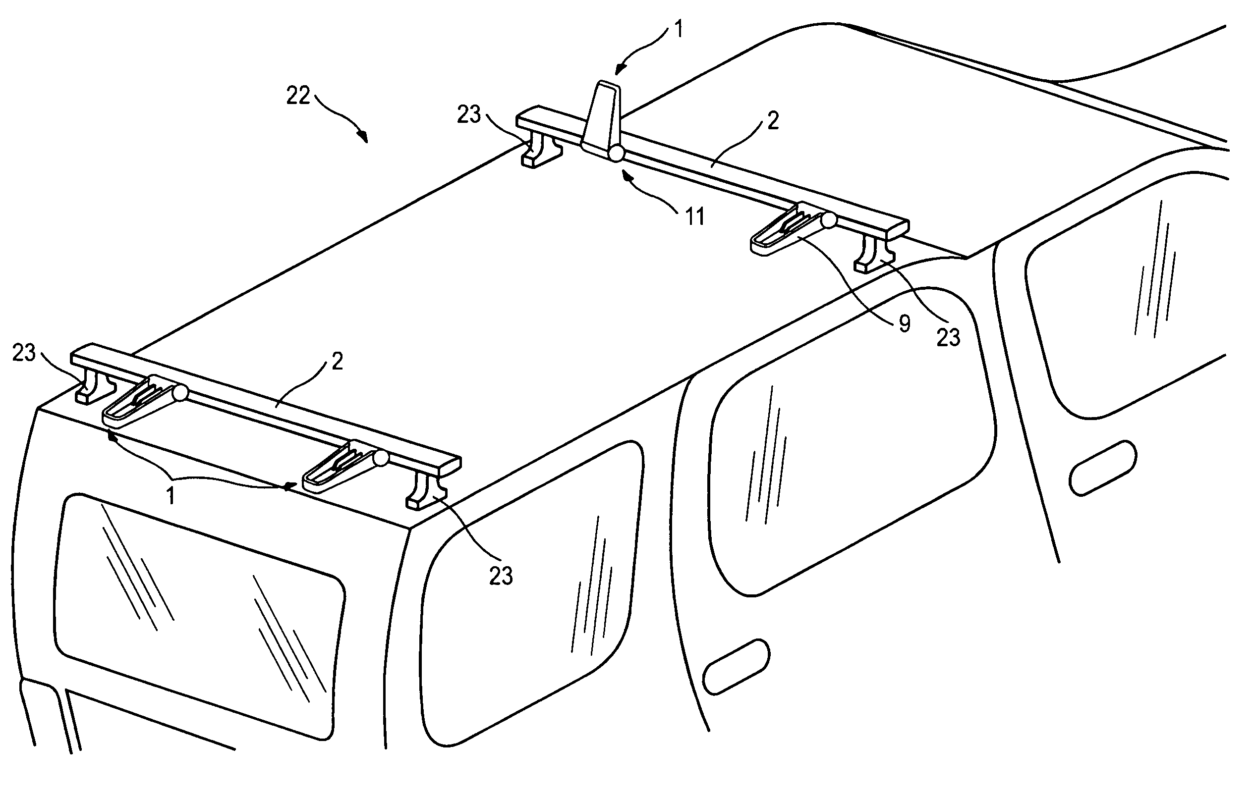
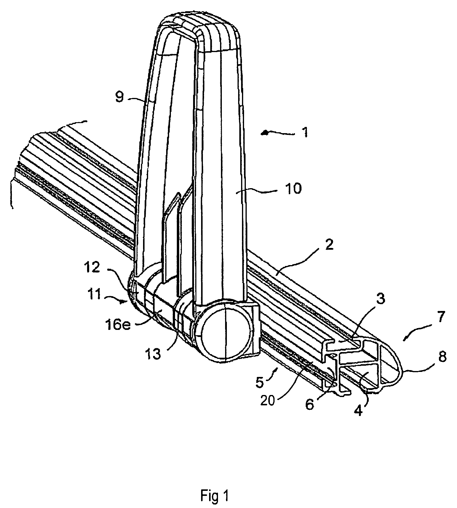
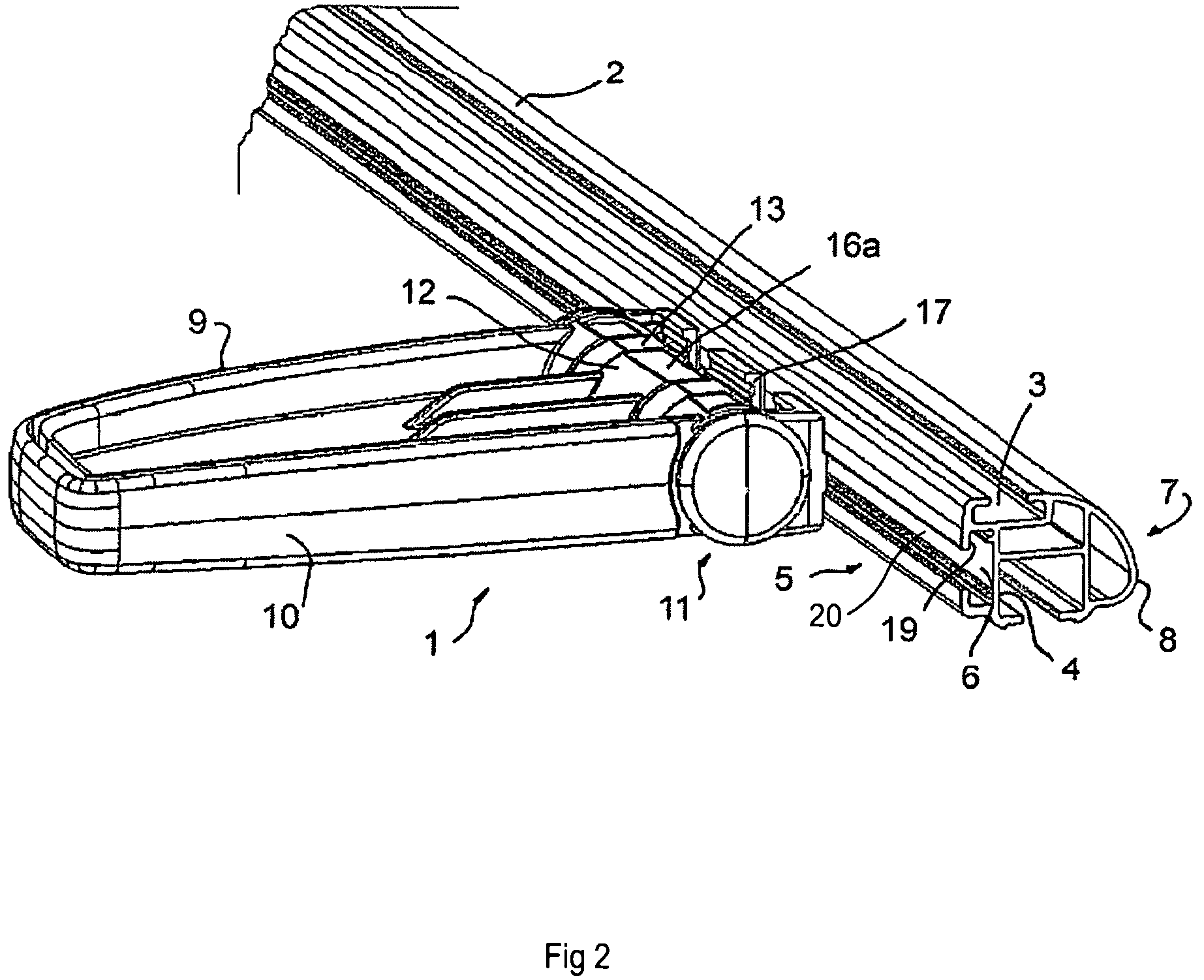
[0012]In FIGS. 1 to 3, a load stop arrangement 1 positioned upon a load carrying tube 2 is shown. The load stop 1 is preferably made of a plastic material, but can also be made of metal. A load carrying tube 2 extends generally between two load carrier feet 23 crosswise over a roof of a vehicle 22 or a truck bed as depicted in FIG. 4. The load carrier feet can in a known manner be fixed at the vehicle or at an existing roof rail of the vehicle. The load carrying tube 2 can be made of aluminium and have an essentially C-shaped groove or receiver 6 for the mounting of accessories thereto by being fastened at the load carrying tube 2 with the aid of a bolt 21. The extension bolt 21 extends through the access slot 20 into the groove 6 and has a rectangular head which can be moved in said groove 6.

[0013]The load carrying tube 2 of the present invention comprises, in addition to an upper C-shaped groove 3 and a lower C-shaped groove 4 used for anchoring the load carrying tube, at least on...


PUM


Abstract

A load stop (1) for supporting a load being transported on a load carrier arranged on a vehicle. The load carrier includes at least one load carrying tube (2) with at least one groove (6) for fastening the load stop on the load carrying tube. The load stop includes an essentially rigid bracket (9) intended to be supportingly arranged adjacent the load. A fastening portion (11) is also provided for mounting the load stop to the load carrying tube. The bracket (9) is pivoted in at the fastening portion (11), wherein the load stop (1) is foldable between at least a raised working position and a folded transporting position.

Description

RELATED CASES[0001]This application is a continuation of International Patent Application Ser. No. PCT / SE2007 / 000613 filed Jun. 26, 2007, titled LOAD STOP FOR SUPPORTING A LOAD ON A LOAD CARRIER, which claims priority to Swedish Patent Application Ser. No. 0601452 filed Jun. 30, 2006. Said applications are expressly incorporated herein by reference in their entirety.BACKGROUND[0002]The present invention refers to a load stop for supporting a load being transported on a load carrier or similar arrangement mounted on a vehicle. The load carrier comprises at least one load carrying tube having at least one groove for fastening the load stop at the load carrying tube. The load stop comprises an essentially rigid bracket configured to be supportingly arranged adjacent the load. The load stop also includes a fastening portion for mounting the load stop at the load carrying tube and the bracket is pivotable in at the fastening portion such that the load stop is foldable between at least a ...

Claims


Application Information

Patent Timeline
Patent Type & Authority Patents(United States)
IPC IPC(8): B60R9/04
CPCB60R9/048F16B37/045F16B2/18
Inventor MAGNUSSON, KARL-JOHAN
Owner THULE SWEDEN AB
Why Eureka
Try Eureka