
Manipulator control method and device, readable storage medium and automation equipment

A control method and manipulator technology, applied in the direction of manipulators, program-controlled manipulators, manufacturing tools, etc., can solve problems such as time-consuming, heavy workload, line of sight, and viewing angle errors, so as to reduce adverse factors, improve production efficiency, and avoid errors. Effect

Active Publication Date: 2020-06-05
SQUAREDOG AI SERVICES LTD
View PDF7 Cites 0 Cited by
  • Summary
  • Abstract
  • Description
  • Claims
  • Application Information

AI Technical Summary

Problems solved by technology

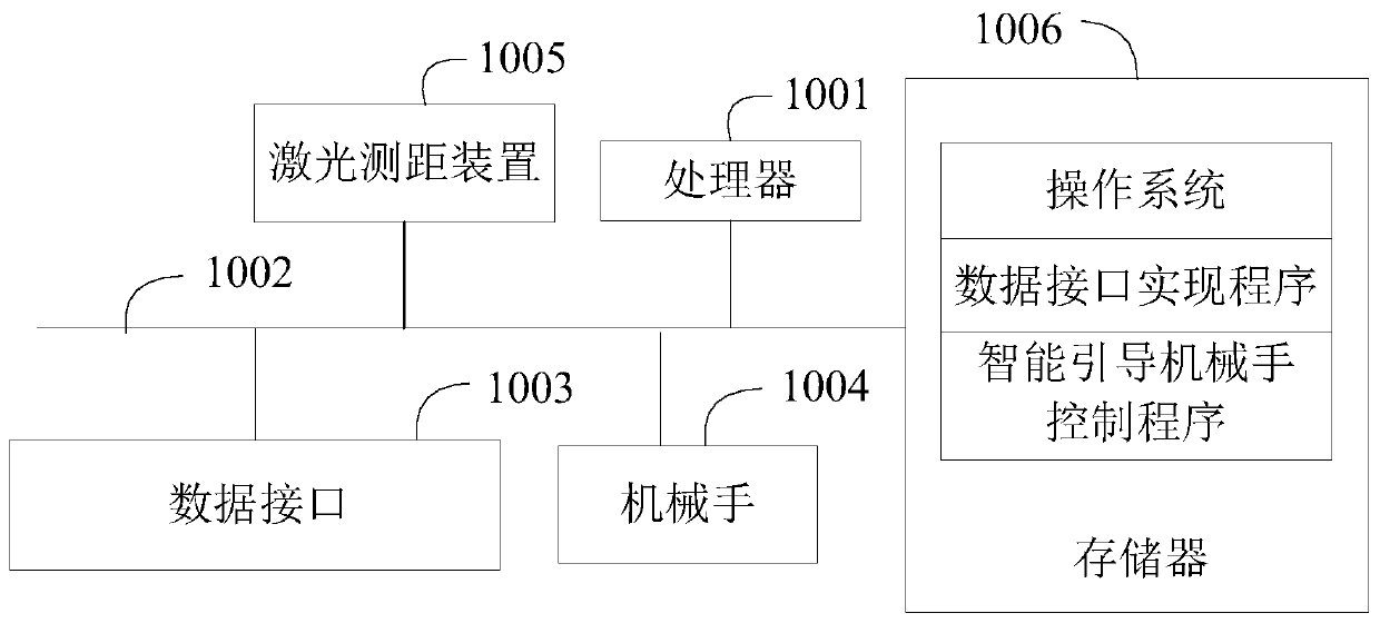
[0002] In the existing industrial technology, the position and working posture of the manipulator in the base coordinate system are usually found by directly moving the manipulator. For workpieces with simple structure, small scale and automatic operation, manipulator debuggers are required to manually Move the manipulator to the surface of the work piece to find the base coordinate system of the manipulator; and for some larger or harsher workpieces, in order to find the base coordinate system of the manipulator during debugging, not only various auxiliary equipment are needed , it may also cause certain hidden dangers to the personal safety of the debugging personnel. At the same time, due to the limitation of the line of sight, directly operating the manipulator to find the coordinate system of the base may cause a collision of the manipulator, causing damage to the manipulator or the workpiece, and may be affected by the line of sight and viewing angle. the problem caused the error
Manual debugging requires debuggers to have certain experience in manipulator debugging, which not only requires a lot of work, but also takes a long time and is inefficient.

Method used


Image

  • Manipulator control method and device, readable storage medium and automation equipment
  • Manipulator control method and device, readable storage medium and automation equipment
  • Manipulator control method and device, readable storage medium and automation equipment

Examples


Embodiment Construction

[0069] The following will clearly and completely describe the technical solutions in the embodiments of the present invention with reference to the accompanying drawings in the embodiments of the present invention. Obviously, the described embodiments are only part of the embodiments of the present invention, not all of them. Based on the embodiments of the present invention, all other embodiments obtained by persons of ordinary skill in the art without creative efforts fall within the protection scope of the present invention.

[0070] It should be noted that if there is a directional indication (such as up, down, left, right, front, back...) in the embodiment of the present invention, the directional indication is only used to explain the position in a certain posture (such as the attached As shown in the figure), if the relative positional relationship, movement conditions, etc. between the various components change, the directional indication will also change accordingly. ...


PUM


Abstract

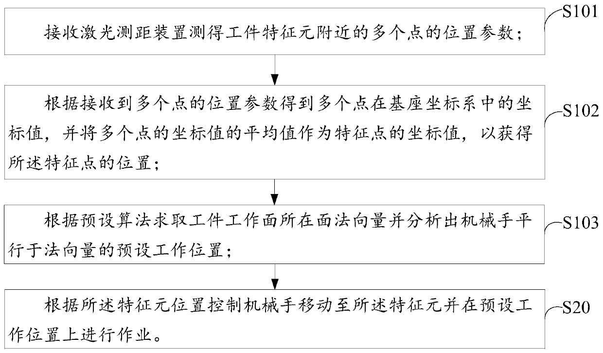
The invention discloses a control method and device for a mechanical hand, a readable storage medium as well as automatic equipment. The control method for the mechanical hand comprises the following steps of: receiving a position parameter, measured by a laser distance measuring device, of a workpiece characteristic element nearby point, and calculating to obtain a characteristic element position in a pedestal coordinate system and a mechanical hand preset working position according to the position parameter; and controlling the mechanical hand to move to a characteristic element according to the characteristic element position and operating on the preset working position. According to the technical scheme adopted by the invention, a working position of a workpiece and a working gesture of the mechanical hand are quickly found through the mechanical hand, so that errors caused by line of sight of staff or visual-angle naked-eye judgment are avoided, adverse factors caused by insufficient debugging experience of staff are reduced, and damages due to the fact the mechanical hand collides with the workpiece when the line of sight is blocked are avoided; and meanwhile, through the technical scheme, the mechanical hand can quickly and precisely search the working position, on the workpiece, of the mechanical hand, so that production efficiency is improved.

Description

technical field [0001] The invention relates to the technical field of industrial automation, in particular to a control method and device for a manipulator, a readable storage medium and automation equipment. Background technique [0002] In the existing industrial technology, the position and working posture of the manipulator in the base coordinate system are usually found by directly moving the manipulator. For workpieces with simple structure, small scale and automatic operation, manipulator debuggers are required to manually Move the manipulator to the surface of the work piece to find the base coordinate system of the manipulator; and for some larger or harsher workpieces, in order to find the base coordinate system of the manipulator during debugging, not only various auxiliary equipment are needed , it may also cause certain hidden dangers to the personal safety of the debugging personnel. At the same time, due to the limitation of the line of sight, directly operat...

Claims


Application Information

Patent Timeline
Patent Type & Authority Patents(China)
IPC IPC(8): B25J9/16B25J13/08
CPCB25J9/1694B25J13/08
Inventor 黎志雄
Owner SQUAREDOG AI SERVICES LTD
Learn More