Packing material fitting structure

a technology of fitting structure and fitting material, which is applied in the direction of engine sealing, machine/engine sealing arrangement, etc., can solve the problems of difficult to verify whether the projection has been reliably and accurately inserted into the cutout portion, and achieve the effect of improving the quality of assembling the packing with the casing, easy to view, and stable fitting sta

Inactive Publication Date: 2012-02-14
YAMADA MANUFACTURING CO LTD
View PDF17 Cites 5 Cited by
  • Summary
  • Abstract
  • Description
  • Claims
  • Application Information

AI Technical Summary

Benefits of technology

[0009]Furthermore, it is difficult to verify whether the projection has been reliably and accurately inserted into the cutout portion. Moreover, when the casing is formed by casting, the fitting groove is usually provided with a draft angle such that the distance between both wall surfaces gradually increases from the bottom portion of the fitting groove to the surface thereof. Because the packing material is fixed to the fitting groove only by the projection and the cutout portion of the fitting groove, the annular portion easily rises from the fitting groove where the draft angle is present. It is an object (technical task) of the present invention to make it possible to mount a packing material very easily on a fitting groove of a casing, to make this mounting strong, and to attain a state in which it would be difficult for the packing material to separate from the casing during transportation thereof as a part.
[0013]In accordance with first aspect of the invention, the main protruding portion of the projection is inserted into the cutout portion, the auxiliary protruding portion and the annular main body portion are inserted into the fitting groove where the cutout portion is formed, and the packing material is fixed to the fitting groove by the main protruding portion and auxiliary protruding portion. Furthermore, outside the projection location, the diameter of the annular main portion has a margin with respect to the width of the fitting groove and the annular main portion does not protrude to the inner circumferential side of the fitting groove. Therefore, the shape of the fitting groove places no limitation on the shape of the entire casing, and a sufficient degree of freedom in designing the casing shape can be ensured. Furthermore, the projection comprises the main protruding portion that is formed to protrude from the annular main body portion and an auxiliary protruding portion that is formed integrally in the vicinity of the main protruding portion, and by apply an external force so as to press the main protruding portion of the projection in the protrusion direction thereof (equivalent to the transverse direction of the projection), it is possible to compress and reduce the size of the main protruding portion and also the auxiliary protruding portion in the transverse direction.
[0015]As described hereinabove, by applying a pressure to the projection in the transverse direction, the auxiliary protruding portion can be reduced in size in the transverse direction. Therefore, the annular main body portion and also the auxiliary protruding portion can be pressed to the bottom portion location of the fitting groove, the annular main body portion and the auxiliary protruding portion can be disposed so as to be in reliable contact with the bottom portion, and a stable fitting state can be produced. Furthermore, when the auxiliary protruding portion of the projection is disposed reliably on the groove bottom portion of the fitting groove and the main protruding portion is in a state of incomplete mounting on the cutout portion, the main protruding portions rises from the lower end of the cutout portion, and because the main protruding portions has a shape inclined in the up-down direction, this state can be easily viewed (see FIG. 6D).
[0016]As a result, incomplete mounting of the main protruding portion on the cutout portion can be prevented, the occurrence of errors in the mounting operation of the packing material on the fitting groove can be prevented and quality of assembling the packing with the casing can be increased. Furthermore, the main protruding portion of the projection is inserted into the cutout portion, the auxiliary protruding portion is inserted together with annular main body portion into the fitting groove, and the main protruding portion is prevented from separating from the cutout portion by a counterforce (elastic pushing force) received by the auxiliary protruding portion from the fitting groove. In addition, because the cross-sectional form of the fitting groove is such that the groove width decreases gradually in the direction toward the groove bottom portion due to a draft angle, the auxiliary protruding portion and the annular main body portion are reliably disposed on the groove bottom portion of the fitting groove, thereby further increasing a force pushing the annular main body portion and the auxiliary protruding portion in the transverse direction. As a result, the packing material can be in a state in which it is even more difficult for the packing material to separate from the fitting groove.
[0017]According to second aspect of the invention, the auxiliary protruding portion of the projection is formed at both sides in the longitudinal direction of the main protruding portions. As a result, in a state in which the main protruding portion has been inserted into the cutout portion, the auxiliary protruding portions are brought into contact with a wall surface of the fitting groove by an adequate pressure at both sides in the transverse direction of the opening of the cutout portion, and the projection location is mounted on the fitting groove in a very stable balanced state. According to third aspect of the invention, the thickness of the auxiliary protruding portion is smaller than the thickness of the main protruding portion. As a result, the auxiliary protruding portion can be easily pushed into the fitting groove.
[0018]According to forth aspect of the invention, the position of the lower surface side of the auxiliary protruding portion substantially coincides with the lower end of the annular main body portion in the diametrical direction. As a result, the auxiliary protruding portion can be reliably disposed at the groove bottom portion of the fitting groove and the packing material can be more reliably mounted on the fitting groove. According to fifth aspect of the invention, because of the fitting structure of a packing material in which the front surface of the auxiliary protruding portion is formed with an inclination such as to approach the annular main body portion side with the transition from the upper surface to the lower surface, the front surface and lower surface of the auxiliary protruding portion can be brought into reliable contact with both groove wall portions and groove bottom portion of the fitting groove provided with a draft angle, and the packing material can be very effectively mounted on the fitting groove.

Problems solved by technology

Furthermore, it is difficult to verify whether the projection has been reliably and accurately inserted into the cutout portion.

Method used


Image

  • Packing material fitting structure
  • Packing material fitting structure
  • Packing material fitting structure

Examples


Embodiment Construction

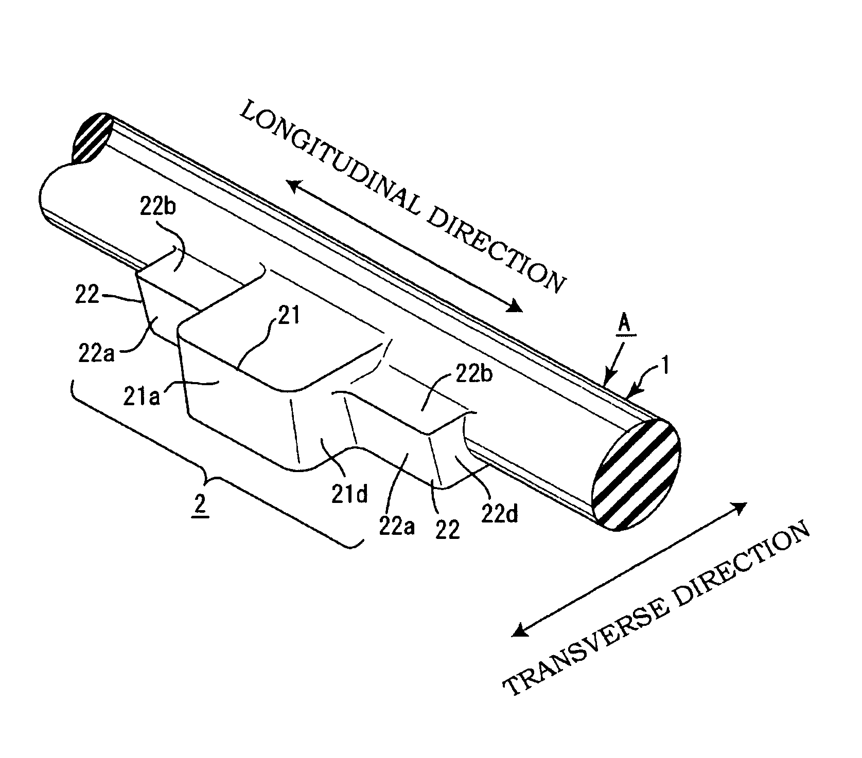
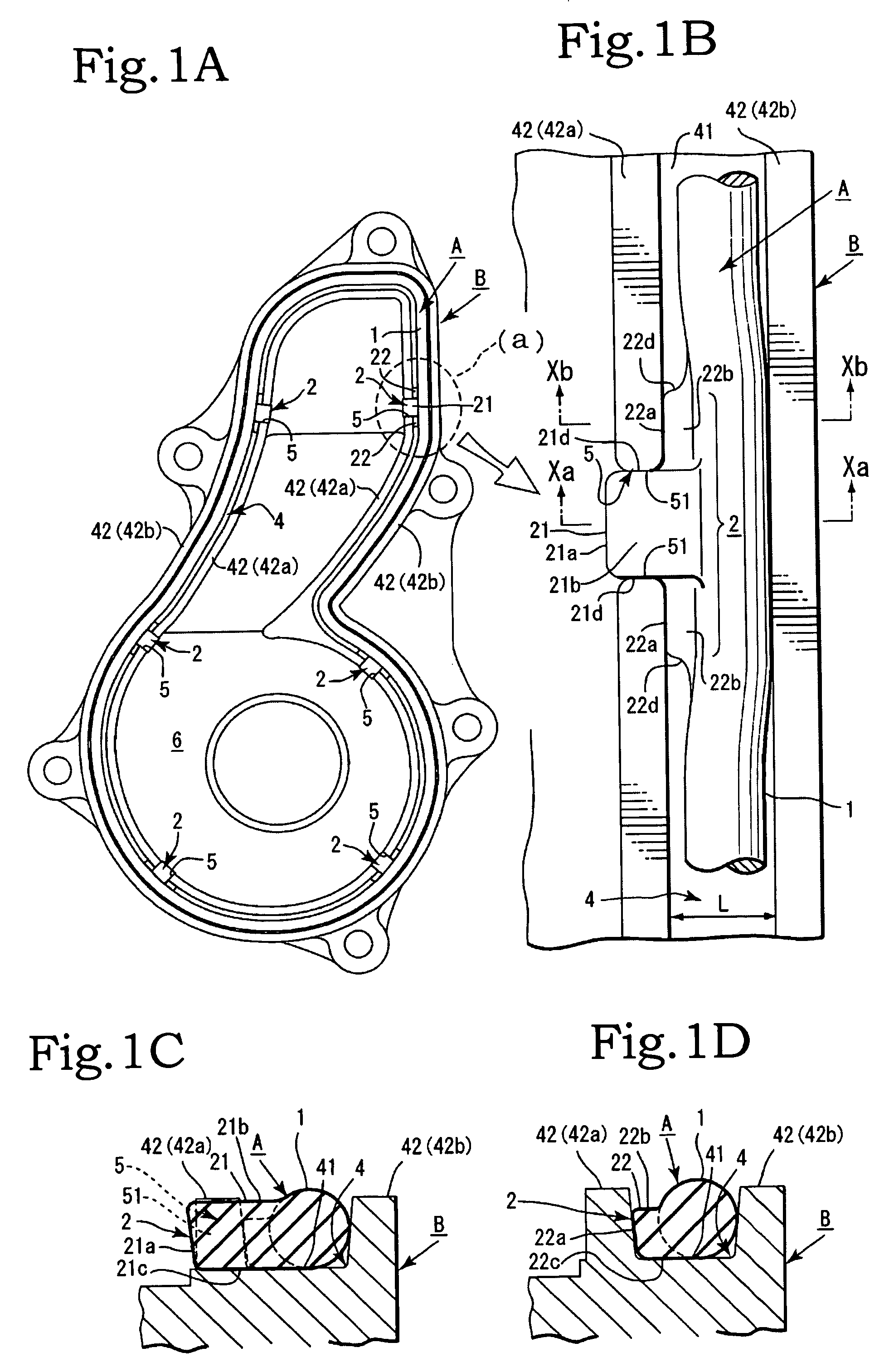
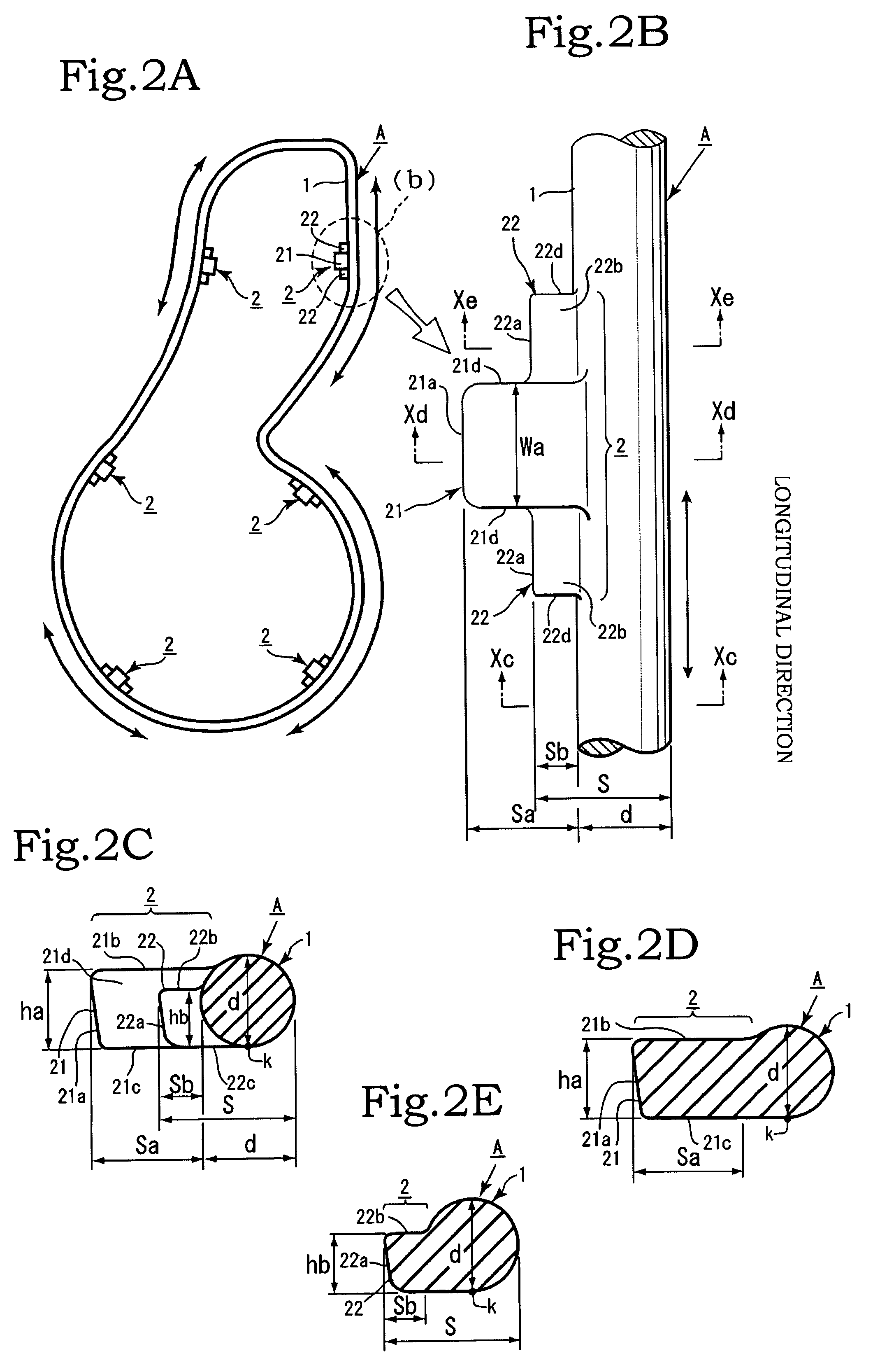
[0025]An embodiment of the present invention will be described below with reference to the appended drawings. As shown in FIG. 1 and FIG. 2, a packing material A is composed of an annular main body portion 1 and a plurality of projections 2, 2, . . . . The plurality of projections 2, 2, . . . are formed with an appropriate spacing along the longitudinal direction of the annular main body portion 1. The longitudinal direction of the annular main body portion 1 is the same direction as the circumferential direction of the annular main body portion 1. The longitudinal direction of the annular main body portion 1 is along the circumference of the annular main body portion 1 (see FIG. 2A). As shown in FIG. 2A, the annular main body portion 1 has an endless annular (loop) shape and is formed to have a shape substantially identical to the shape in the longitudinal direction of a fitting groove 4 of the below-described casing B. The annular main body portion has a definite shape such as a r...


PUM


Abstract

A packing material fitting structure that prevents the packing material from easily dropping out and facilitates mounting and fixing of the packing material in a packing material fitting place in a part such as a casing or a cover of an engine or a pump with sealing ability. The fitting structure is provided with a packing material having an annular main body portion and a plurality of projections each having a main protruding portion formed to protrude from the annular main body portion and an auxiliary protruding portion formed integrally in the vicinity of the main protruding portion, the projections being formed with an appropriate spacing in the longitudinal direction of the main annular main body portion. The fitting structure is also provided with a casing having formed therein an annular fitting groove for inserting the annular main body portion of the packing material. A cutout portion into which only the main protruding portion of the projection is inserted is formed in a groove wall portion of the fitting groove. An integral forming region of the auxiliary protruding portion and the annular main body portion has a width substantially equal to or larger than a width of the fitting groove. In the packing material, a projection formation location is pressed and fixed only by the cutout portion and both groove wall portions in the vicinity of the cutout portion.

Description

BACKGROUND OF THE INVENTION[0001]1. Field of the Invention[0002]The present invention relates to a packing material fitting structure such that the packing material can be prevented from easily separating or dropping out of a fitting groove in a packing material fitting place in a part such as a casing or a cover of an engine or a pump with sealing property, the packing material can be easily mounted and fixed, and the sealing ability in the packing material fixing place can be prevented from decreasing.[0003]2. Description of the Related Art[0004]Packing materials have been widely used in portions requiring sealing ability in parts such as casings and covers of engines, pumps, and the like. An annular (loop-shaped) groove is formed in a joining surface to mount the packing material between the joining surfaces of structural members such as casings and covers, and a packing material of a similar annular shape is mounted along the longitudinal direction of the fitting groove. In most...

Claims


Application Information

Patent Timeline
Patent Type & Authority Patents(United States)
IPC IPC(8): F16J15/10F02F11/00
CPCF16J15/061F16J15/062F16J15/106
Inventor YOSHIDA, HARUYOSHI
Owner YAMADA MANUFACTURING CO LTD
Why Eureka
Try Eureka