
Walking assisting device

a technology of walking aids and walking aids, which is applied in the field of walking aids, can solve the problems of large apparatus size, user's feeling, and inability to use in a small place, and achieve the effect of reducing the size of the connection

Active Publication Date: 2012-02-14
HONDA MOTOR CO LTD
View PDF13 Cites 17 Cited by
  • Summary
  • Abstract
  • Description
  • Claims
  • Application Information

AI Technical Summary

Benefits of technology

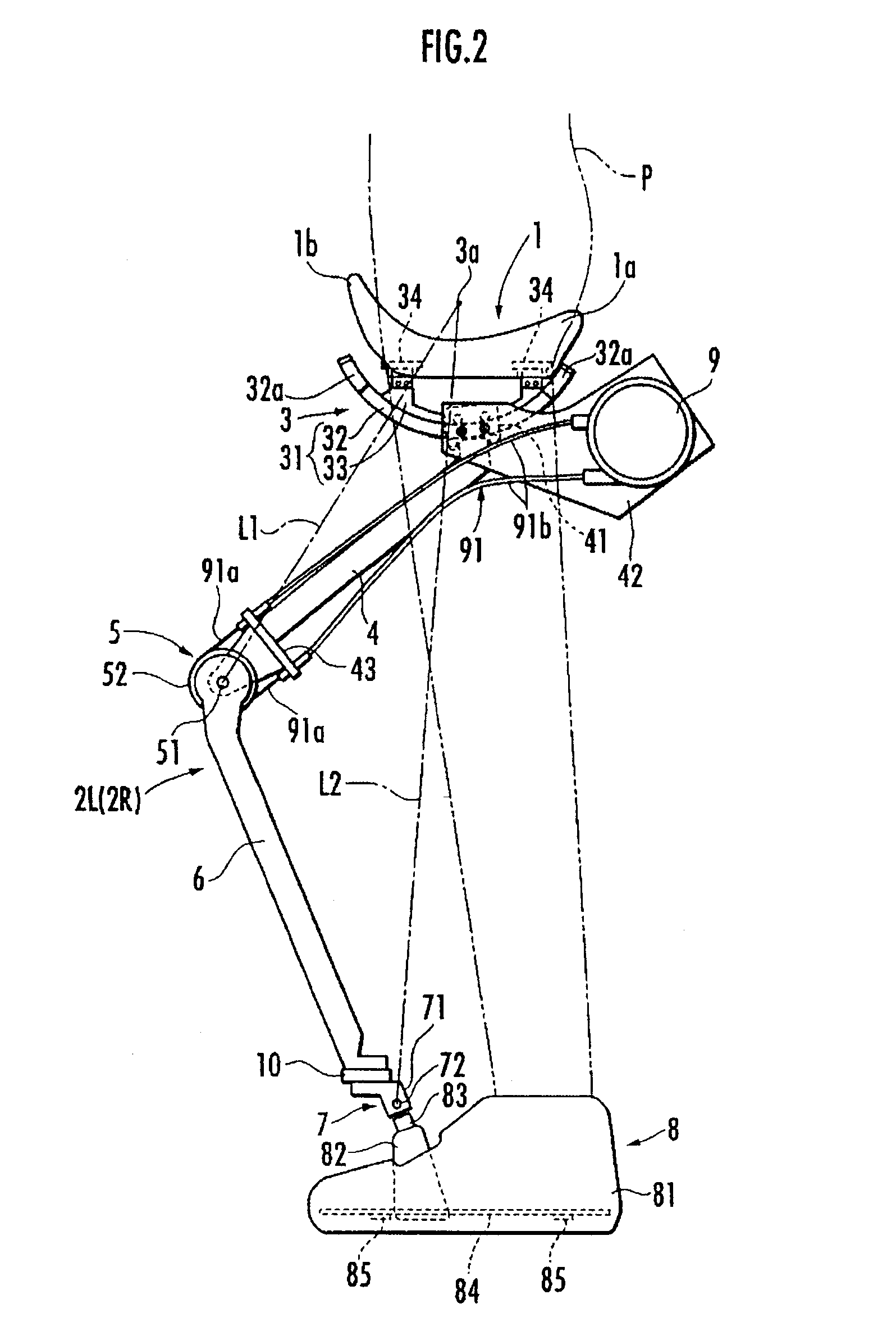
[0011]Where the forward / backward swinging fulcrum of the leg link is located above the sitting member as described above, the action point of the weight is displaced backward under the forward / backward swinging fulcrum of the leg link if the action point of the weight of the user's upper body relative to the sitting member is misaligned forward of the forward / backward swinging fulcrum of the leg link and the sitting member inclines forward and downward. Therefore, the anteroposterior distance between the fulcrum and the action point of the weight decreases, which also decreases the rotation moment applied to the sitting member. Thereafter, when the action point of the weight is displaced up to the position just under the forward / backward swinging fulcrum of the leg link, the rotation moment applied to the sitting member becomes zero, which stabilizes the sitting member in this state. The sitting member thus automatically converges on the stable state in this way, which thereby prevents the sitting member from being misaligned in the forward / backward direction under the user's crotch.
[0012]Furthermore, when the lateral swinging fulcrum of the leg link is located above the sitting member, the action point of the weight is displaced laterally inward under the lateral swinging fulcrum of the leg link if the action point of the weight is misaligned laterally outward of the lateral swinging fulcrum of the leg link and the sitting member inclines laterally, and thereby the lateral distance between the fulcrum and the action point of the weight decreases. Therefore, the rotation moment applied to the sitting member decreases, too. Thereafter, when the action point of the weight is displaced up to the position just under the lateral swinging fulcrum of the leg link, the rotation moment applied to the sitting member becomes zero, which stabilizes the sitting member in this state.
[0013]Thus, according to the present invention, the stability of the sitting member can be improved in spite of the leg link coupled to the connection on the undersurface of the sitting member and therefore a compact and easy-to-use walking aid apparatus can be achieved.
[0015]Where the leg link is composed of a freely bending and stretching link having a rotary joint in the middle thereof or a retractable link having a direct acting joint in the middle thereof, it is possible to generate bearing power for supporting at least a part of the user's weight by providing biasing means for biasing the joint in the stretching direction (in the direction of pushing up the sitting member). Preferably, however, a driving source should be provided for driving the joint located in the middle of the leg link. According thereto, it is possible to aid the user in walking properly by generating bearing power according to a load on the user's foot with the control of the driving source.
[0016]Moreover, if the upper end of the leg link movably engages with an arc-shaped guide track longitudinal in the forward / backward direction and having the center of curvature above the sitting member and if the leg link is composed of a freely bending and stretching link having a rotary joint in the middle thereof, it is desirable to adapt the upper end of the leg link so as to engage with a portion of the guide track located backward of a line between the middle joint and the center of curvature (the forward / backward swinging fulcrum of the leg link) of the guide track. This enables securing the forward swinging stroke of the leg link that follows the forward swinging motion of a user's leg without a need for a guide track particularly long in the forward direction. Therefore, the connection can be reduced in size advantageously.

Problems solved by technology

Therefore, the user becomes susceptible to a feeling of being bound.
Furthermore, since the first joints of the right and left leg links are projecting on both sides of the user's waist, the user often hits his hands against the first joints or the upper parts of the leg links coupled to the first joints when swinging his arms while walking inconveniently.
Although this embodiment reduces the user's feeling of being bound, the apparatus is large in size and cannot be used in a small place.
Furthermore, the user often hits his hands against the frame when swinging his arms while walking.
Therefore, it cannot improve the usability.
As set forth in the above, there are various problems in the conventional walking aid apparatuses.
Moreover, the user only needs to sit astride the sitting member, which reduces the user's feeling of being bound.

Method used


Image

  • Walking assisting device
  • Walking assisting device
  • Walking assisting device

Examples


Embodiment Construction

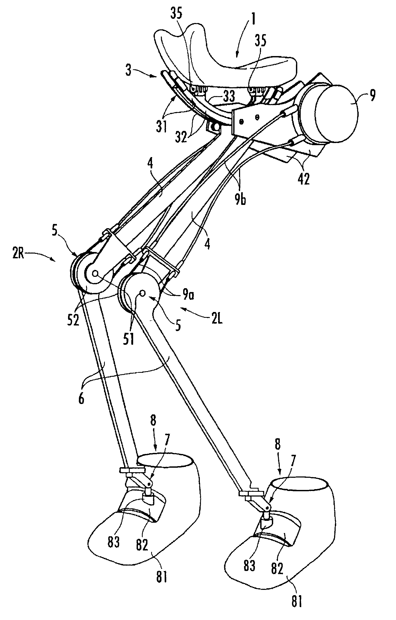
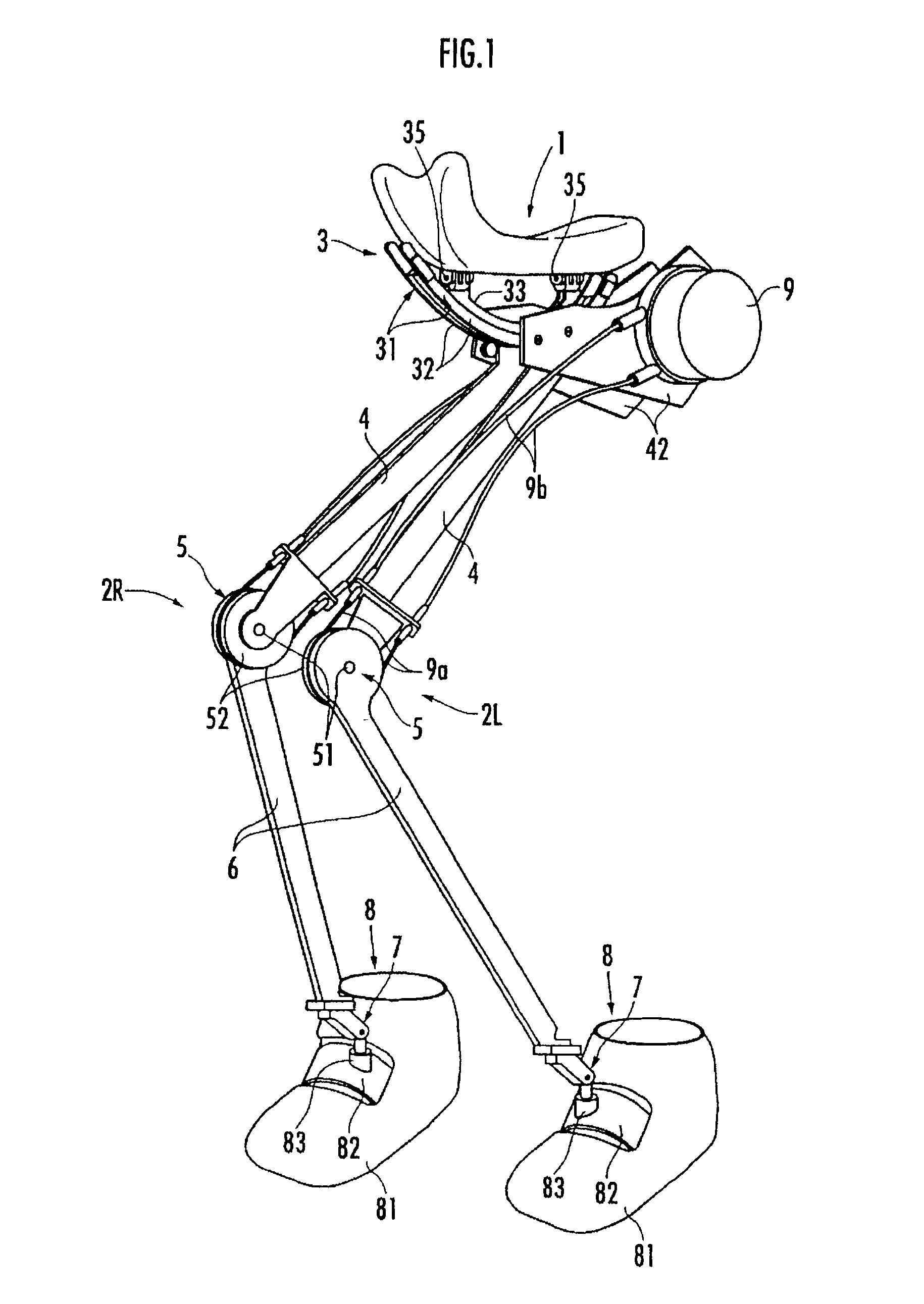
[0027]A walking aid apparatus according to preferred embodiments of the present invention will be described hereinafter. As shown in FIG. 1 to FIG. 3, the walking aid apparatus includes a sitting member 1 serving as a load transmit section which a user P sits astride and a pair of left and right leg links 2L and 2R attached under the sitting member 1.

[0028]The leg links 2L and 2R are each composed of a freely bending and stretching link having a first link 4 coupled to a first joint 3 functioning as a connection provided on the undersurface of the sitting member 1 and a second link 6 coupled to the lower end of the first link 4 via a rotary second joint 5. In addition, the lower end of the second link 6 is coupled to a landing member 8 attached to each of the user's right and left feet via a third joint 7. Furthermore, the leg links 2L and 2R are each equipped with a driving source 9 for the second joint 5. Then, the driving source 9 is used to rotationally drive the second joint 5 ...


PUM


Abstract

A walking aid apparatus comprising a sitting member which a user sits astride and leg links each coupled to a connection provided on the undersurface of the sitting member in such a way as to be free to swing in the forward / backward direction, which improves the stability of the sitting member. The connection is adapted in such a way that a forward / backward swinging fulcrum of the leg links is located above the sitting member. More specifically, the connection is provided with an arc-shaped guide track longitudinal in the forward / backward direction and having the center of curvature above the sitting member, so that each of the leg links swings along the guide track in the forward / backward direction. If the leg links are allowed to swing freely also in the lateral direction, preferably the lateral swinging fulcrum of the leg links is also located above the sitting member.

Description

BACKGROUND OF THE INVENTION[0001]The present invention relates to a walking aid apparatus for aiding a user in walking.BACKGROUND ART[0002]Conventionally, there is already known this type of walking aid apparatus that is provided with a waist support belt attached around a user's waist with a pair of right and left leg links coupled to each other via first joints corresponding to the hip joints of a person on both sides of the waist support belt in the lateral direction (for example, refer to Japanese publication of patent application No. 2003-220102). In this apparatus, each leg link is formed of a freely bending and stretching link, which has a second joint corresponding to the knee joint of the person vertically in the middle of the leg link, with the lower end of the leg link being coupled to a landing member attached to a user's foot. In addition, the walking aid apparatus includes a driving source for the second joint to generate bearing power for supporting a part of a user's...

Claims


Application Information

Patent Timeline
Patent Type & Authority Patents(United States)
IPC IPC(8): A61H1/00A61H3/00
CPCA61H3/00A61H3/008B25J9/0006A61H1/024A61H2201/1633A61H2201/165A61H2201/50A61H2201/5061A61H2201/5071A61H2201/1215A61H2201/1409A61H2201/1642A61H2201/1676
Inventor IKEUCHI, YASUSHINODA, TATSUYAASHIHARA, JUNHIKI, YUTAKA
Owner HONDA MOTOR CO LTD
Learn More