Filament power supply circuit for vacuum fluorescent display

a technology of vacuum fluorescent display and power supply circuit, which is applied in the direction of instruments, light sources, electrical equipment, etc., can solve the problems of large power loss, low reliability, and degraded display quality, and achieve the effect of suppressing the degradation of display quality

Active Publication Date: 2012-02-14
NORITAKE ITRON CORP +1
View PDF6 Cites 6 Cited by
  • Summary
  • Abstract
  • Description
  • Claims
  • Application Information

AI Technical Summary

Benefits of technology

[0015]It is an object of the present invention to suppress degradation in the display quality of a vacuum fluorescent display when a DC power supply voltage Vcc varies.

Problems solved by technology

However, when an AC voltage is doubled and rectified, power loss is large.
Additionally, since the voltage doubling circuit becomes hot, the reliability lowers.
This causes variations in the amount of electrons emitted by the filament, and degrades the display quality, resulting in, e.g., shorter life of the vacuum fluorescent display or flickering display.

Method used


Image

  • Filament power supply circuit for vacuum fluorescent display
  • Filament power supply circuit for vacuum fluorescent display
  • Filament power supply circuit for vacuum fluorescent display

Examples


Embodiment Construction

[0023]The embodiment of the present invention will now be described with reference to the accompanying drawings.

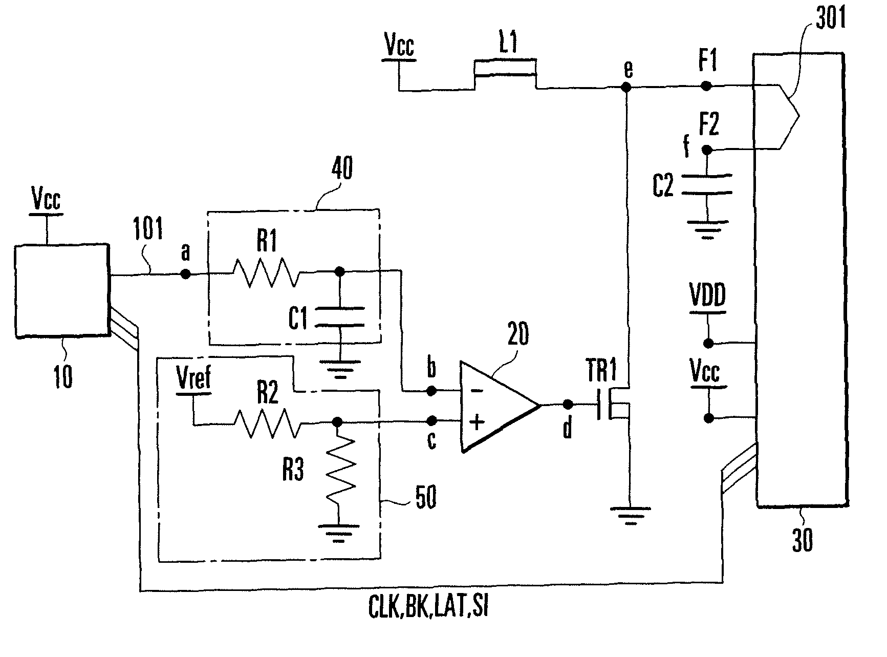
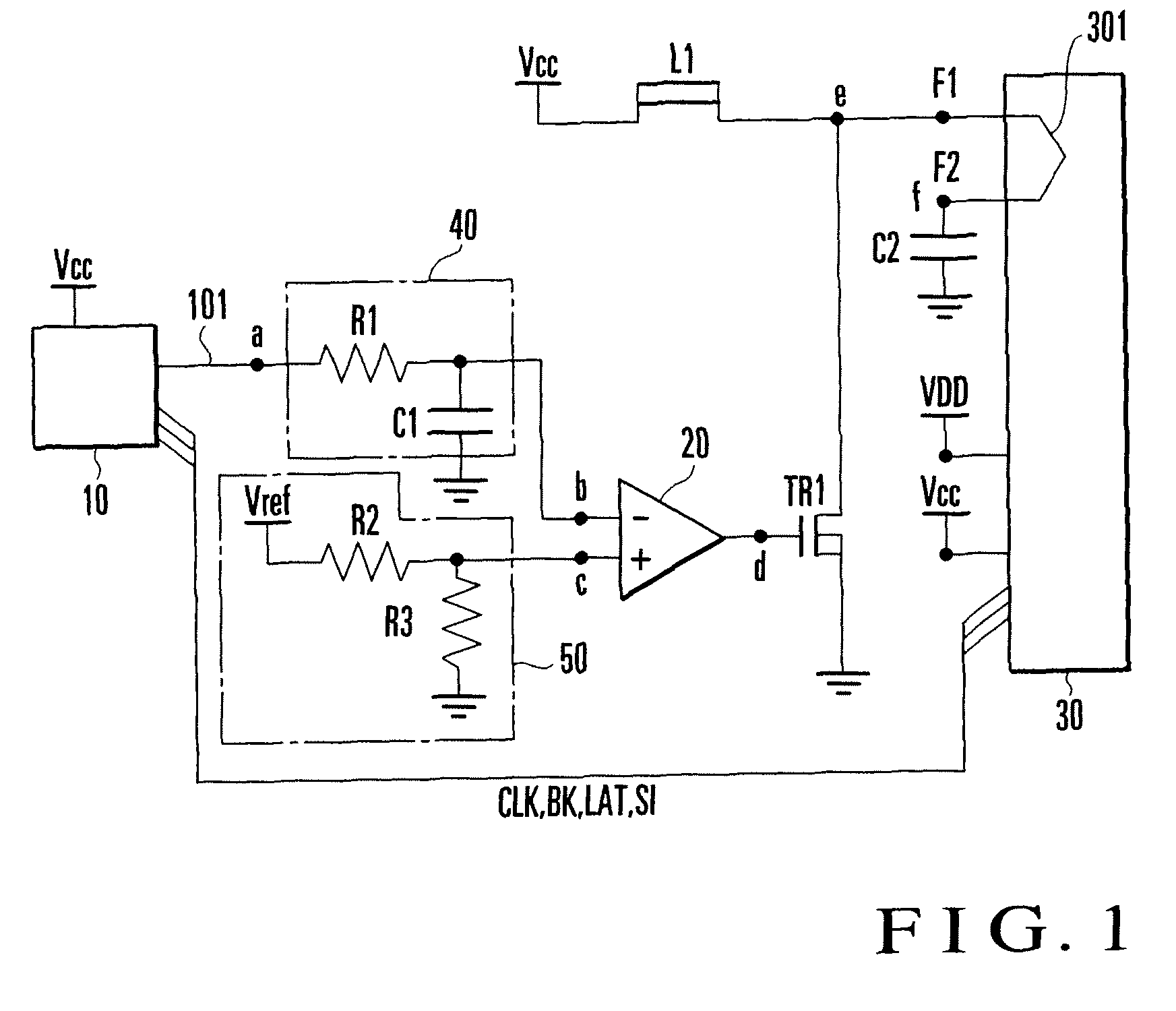
[0024]Referring to FIG. 1, a VFD (Vacuum Fluorescent Display) 30 is formed by accommodating, in an evacuated container made of, e.g., glass, an anode (not shown) formed on a substrate and having a fluorescent material applied, a filament cathode 301 separately arranged above the anode, and a grid electrode (not shown) arranged between the anode and the filament cathode.

[0025]The VFD 30 includes filament cathode connection terminals F1 and F2 to which a filament voltage supplied from a filament power supply circuit (to be described later) is applied, power supply terminals to which a DC voltage VDD for a display voltage and a DC power supply voltage Vcc (about 5 V) are applied, and signal input thermals for receiving various kinds of signals CLK, BK, LAT, and SI supplied from an external device (CPU 10 for VFD driving) for driving and display of the VFD 30.

[0026]Note that t...


PUM


Abstract

In a filament power supply circuit of a vacuum fluorescent display, an integration circuit is connected to a signal input terminal which receives a pulse signal having a magnitude corresponding to a DC power supply voltage. A comparison circuit compares an output voltage from the integration circuit with a reference voltage, and outputs a result. A first filament cathode connection terminal is connected to one terminal of the filament cathode of a vacuum fluorescent display and applies the DC power supply voltage to the one terminal. A second filament cathode connection terminal is connected to the other terminal of the filament cathode to ground the other terminal via a capacitive element. A three-terminal element includes first, second, and third terminals. The first terminal is connected to the first filament cathode connection terminal. The second terminal is grounded. The third terminal receives the output from the comparison circuit so that the path between the first terminal and the second terminal is switched in accordance with it.

Description

BACKGROUND OF THE INVENTION[0001]The present invention relates to a driving circuit for a vacuum fluorescent display and, more particularly, to a driving circuit for supplying power to the filament of a vacuum fluorescent display.[0002]A vacuum fluorescent display is an electron tube which accommodates an anode and a cathode in an evacuated container (envelope) having at least one transparent side surface. The vacuum fluorescent display normally has a triode structure having, between the anode and the cathode, a grid to control movement of electrons emitted by the cathode. In this vacuum fluorescent display, the grid accelerates electrons emitted by the cathode to make them collide against phosphor applied onto the anode. Then, the phosphor emits light, and a desired pattern is displayed.[0003]The cathode normally uses a filament with an electron emission material applied. Power is supplied to the filament to make it generate heat, thereby generating thermoelectrons.[0004]To drive t...

Claims


Application Information

Patent Timeline
Patent Type & Authority Patents(United States)
IPC IPC(8): H05B41/36
CPCH05B41/295
Inventor MOROOKA, NAOYUKIAKIYAMA, MIZUKISHIBATA, KAZUHISAKOHAMA, TORU
Owner NORITAKE ITRON CORP
Why Eureka
Try Eureka