
Electronic device with two image sensors

a technology of image sensor and electronic device, which is applied in the direction of selective content distribution, television system, color signal processing circuit, etc., can solve the problems of insufficient luma data and chroma data received limited thickness reduction, and insufficient luma data and chroma data for constructing an image of an obj

Active Publication Date: 2012-02-14
APPLE INC
View PDF11 Cites 116 Cited by
  • Summary
  • Abstract
  • Description
  • Claims
  • Application Information

AI Technical Summary

Benefits of technology

The present invention is about an electronic device that can create an air image of an object. It includes a black-and-white camera and a color camera that capture luma and chroma data about the object. The device uses logic to correlate the luma data with the chroma data and adjust the color data based on the luma data to create the air image. The technical effect of this invention is to provide a more accurate and realistic air image of an object through the use of both luma and chroma data.

Problems solved by technology

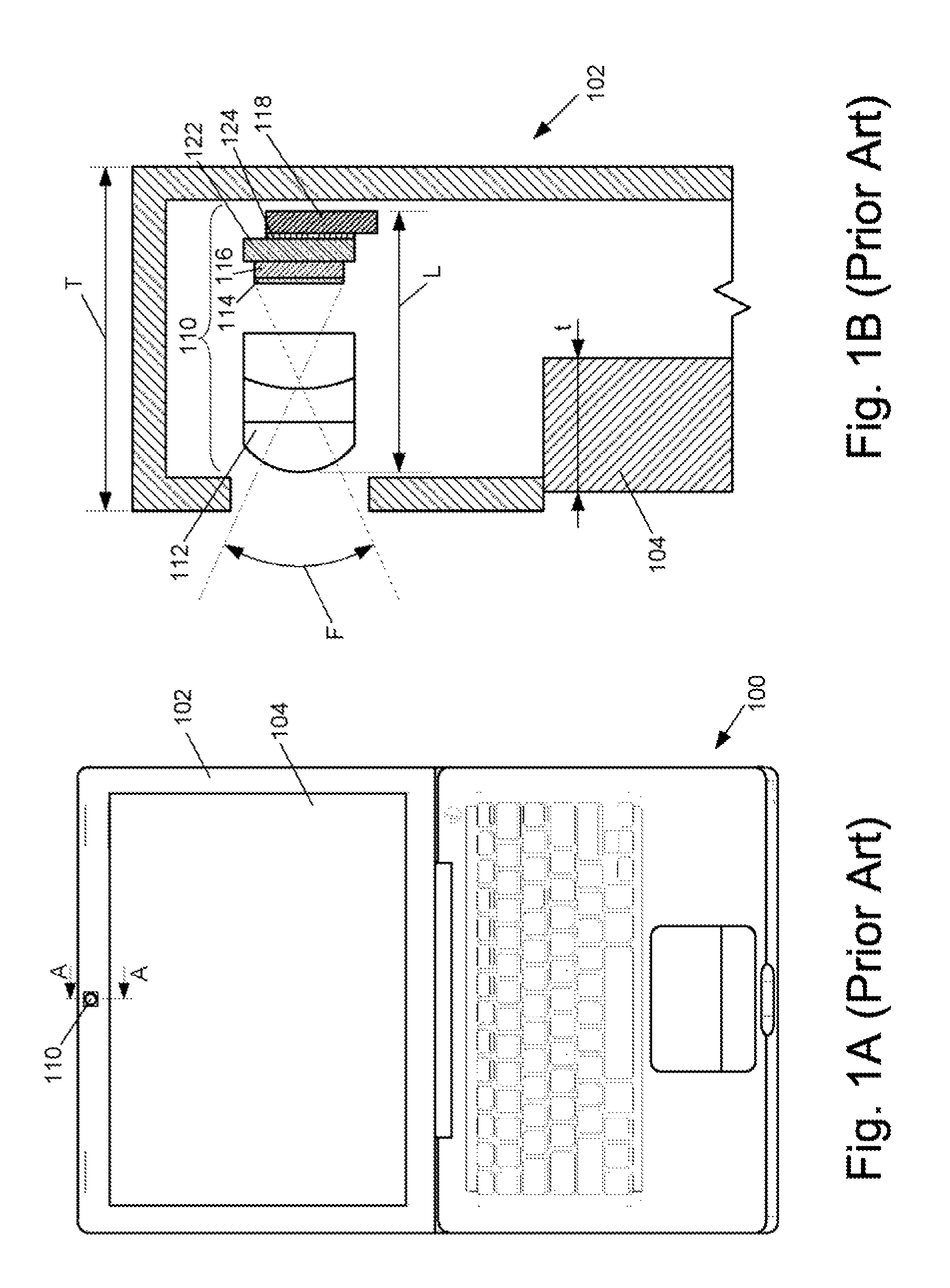
However, for an electronic device equipped with a camera, given image quality requirements, thickness reduction may be limited by the track length of the camera, as discussed with the reference to the examples of FIGS. 1A-B.
However, if the number of photo sensors is reduced, the luma data and chroma data received for constructing an image of the object may be insufficient.
As a result, the quality of the constructed image may be compromised.
However, if the pitch is reduced, the light received by the photo sensors may be insufficient.
As a result, the image quality may not be acceptable.
However, the luma received by the color image sensor may not be sufficient.
As a result, the quality of the reconstructed image will be compromised.

Method used


Image

  • Electronic device with two image sensors
  • Electronic device with two image sensors
  • Electronic device with two image sensors

Examples


Embodiment Construction

[0027]The present invention will now be described in detail with reference to a few embodiments thereof as illustrated in the accompanying drawings. In the following description, numerous specific details are set forth in order to provide a thorough understanding of the present invention. It will be apparent, however, to one skilled in the art, that the present invention may be practiced without some or all of these specific details. In other instances, well known process steps and / or structures have not been described in detail in order to not unnecessarily obscure the present invention.

[0028]Various embodiments are described herein below, including methods and techniques. It should be kept in mind that the invention might also cover an article of manufacture that includes a computer readable medium on which computer-readable instructions for carrying out embodiments of the inventive technique are stored. The computer readable medium may include, for example, semiconductor, magneti...


PUM


Abstract

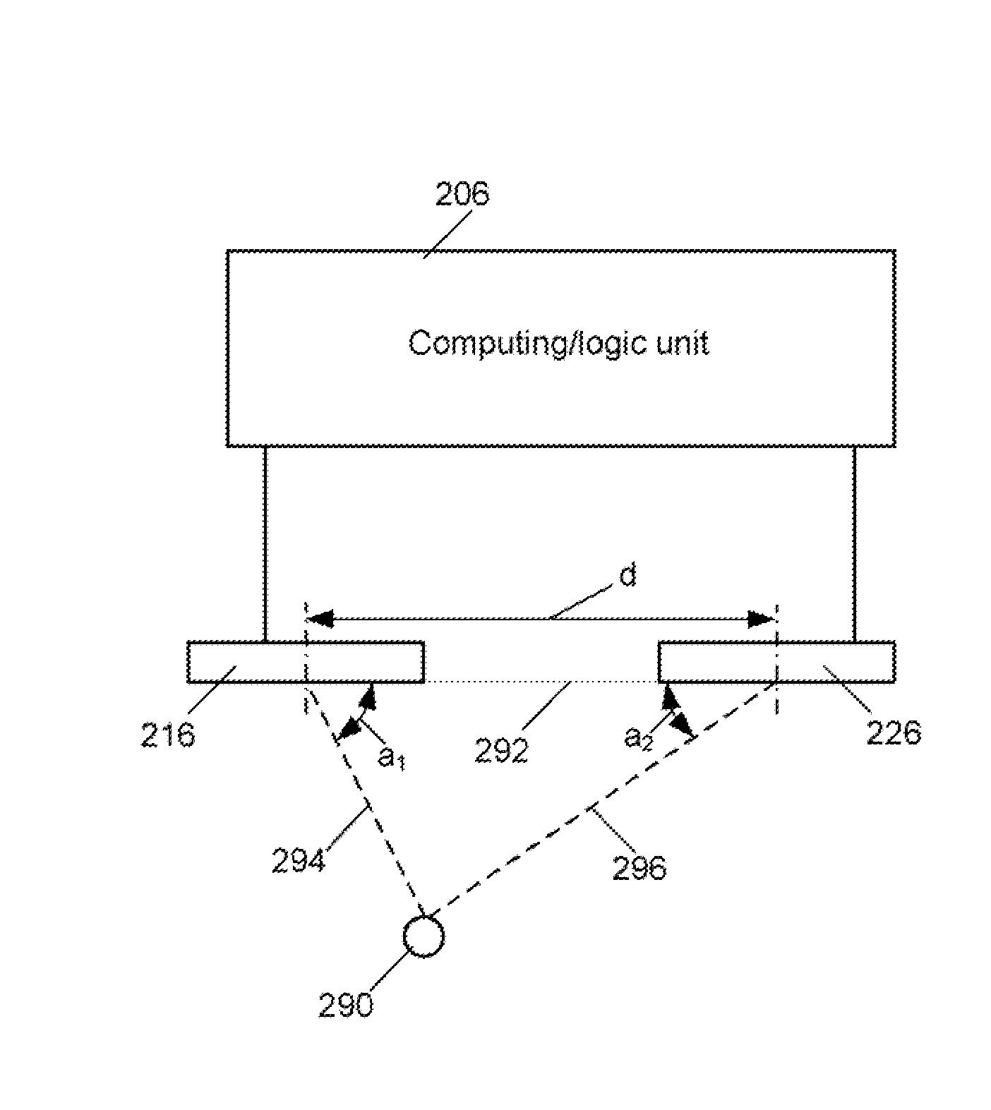
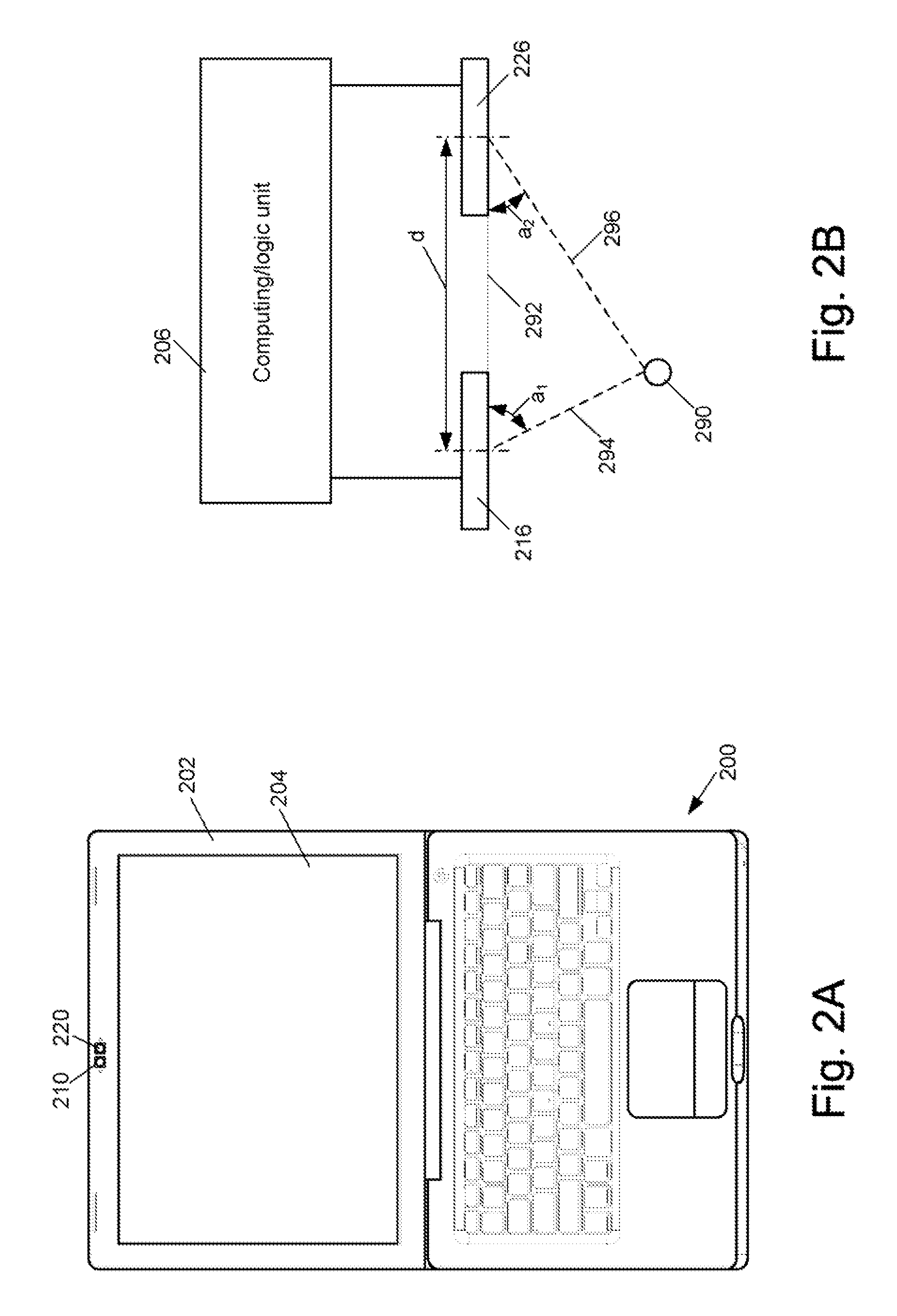
An electronic device for producing an image of an object is disclosed. The electronic device may include a black-and-white camera having a first sensor area configured to receive luma data pertaining to the object. The first sensor area may correspond to a first pixel array, the luma data associated with the first pixel array. The electronic device may also include a color camera having a second sensor area configured to receive chroma data pertaining to the object. The second sensor area may correspond to a second pixel array. The chroma data may be associated with the second pixel array. The electronic device may also include first logic configured to correlate pixels in the first pixel array with locations on the second sensor area.

Description

BACKGROUND OF THE INVENTION[0001]Due to industrial design requirements for usability, aesthetics, etc., it is generally desirable to reduce the thickness of an electronic device, for example, a notebook computer or cellular phone. However, for an electronic device equipped with a camera, given image quality requirements, thickness reduction may be limited by the track length of the camera, as discussed with the reference to the examples of FIGS. 1A-B.[0002]FIG. 1A illustrates a schematic representation of an example prior art electronic device 100 equipped with a color camera 110. Color camera 110 may be installed in a display module 102, which includes a display unit 104.[0003]FIG. 1B illustrates a schematic representation of a partial cross-sectional view through line A-A of electronic device 100 indicated in the example of FIG. 1A. As illustrated in the example of FIG. 1B, color camera 110 may include a lens 112 configured to receive reflected light from an object.[0004]Color cam...

Claims


Application Information

Patent Timeline
Patent Type & Authority Patents(United States)
IPC IPC(8): H04N9/73
CPCH04N5/2253H04N5/772H04N9/045H04N21/41407H04N21/4223H04N23/54H04N23/50H04N23/843
Inventor CULBERT, MICHAEL FLIGTENBERG, CHRIS
Owner APPLE INC
Learn More