
Methods and systems for detecting small span loss changes in fiber optic networks

a fiber optic network and small span technology, applied in the field of optical networking, can solve the problems of inability to adapt mechanisms to single-mode fiber, inability to achieve fixed-size fiber optic networks, and inability to use non-standard hardwar

Active Publication Date: 2012-02-14
CIENA
View PDF8 Cites 8 Cited by
  • Summary
  • Abstract
  • Description
  • Claims
  • Application Information

AI Technical Summary

Benefits of technology

The present invention provides methods and systems for detecting small changes in fiber optic networks. The methods involve measuring power changes at both ends of a fiber span and calculating the fiber span loss by integrating these changes. The system includes a computer that requests power measurements, calculates the fiber span loss, stores it, and time averages it to detect small changes over time. The invention can detect fiber taps and degradation in the fiber span, providing early detection of potential network issues. The technical effects of the invention include improved accuracy in detecting fiber optic network changes and improved network monitoring.

Problems solved by technology

If the solution requires non-standard hardware, it may not be a feasible solution since the costs associated with using non-standard hardware generally outweigh the benefits.
However, single-mode fiber typically dominates network infrastructures since its dispersive properties are more easily managed compared to multi-mode fiber, and these mechanisms are not adaptable to single-mode fiber.
If the solution requires additional hardware, both the cost and complexity of the system increase.
While satisfying the first and second criteria, the technique does not satisfy the third criteria since it is not capable of measuring small span loss changes (e.g., <1% power change).
This limitation is rooted in the assumption that the nominal OSC-Tx is constant.

Method used


Image

  • Methods and systems for detecting small span loss changes in fiber optic networks
  • Methods and systems for detecting small span loss changes in fiber optic networks
  • Methods and systems for detecting small span loss changes in fiber optic networks

Examples


Embodiment Construction

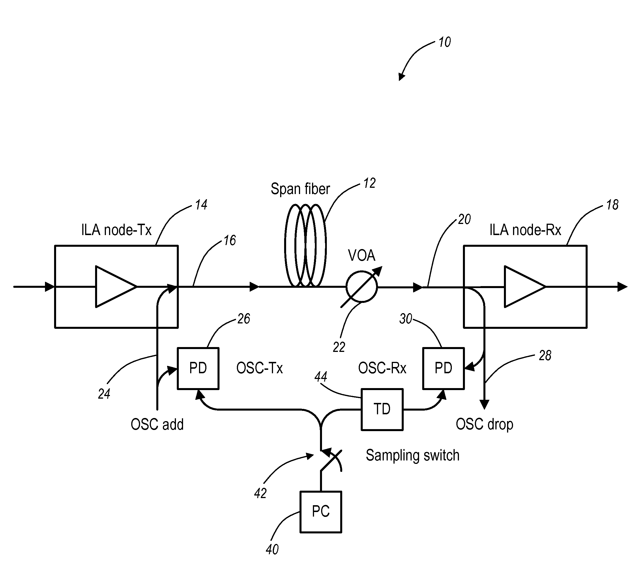
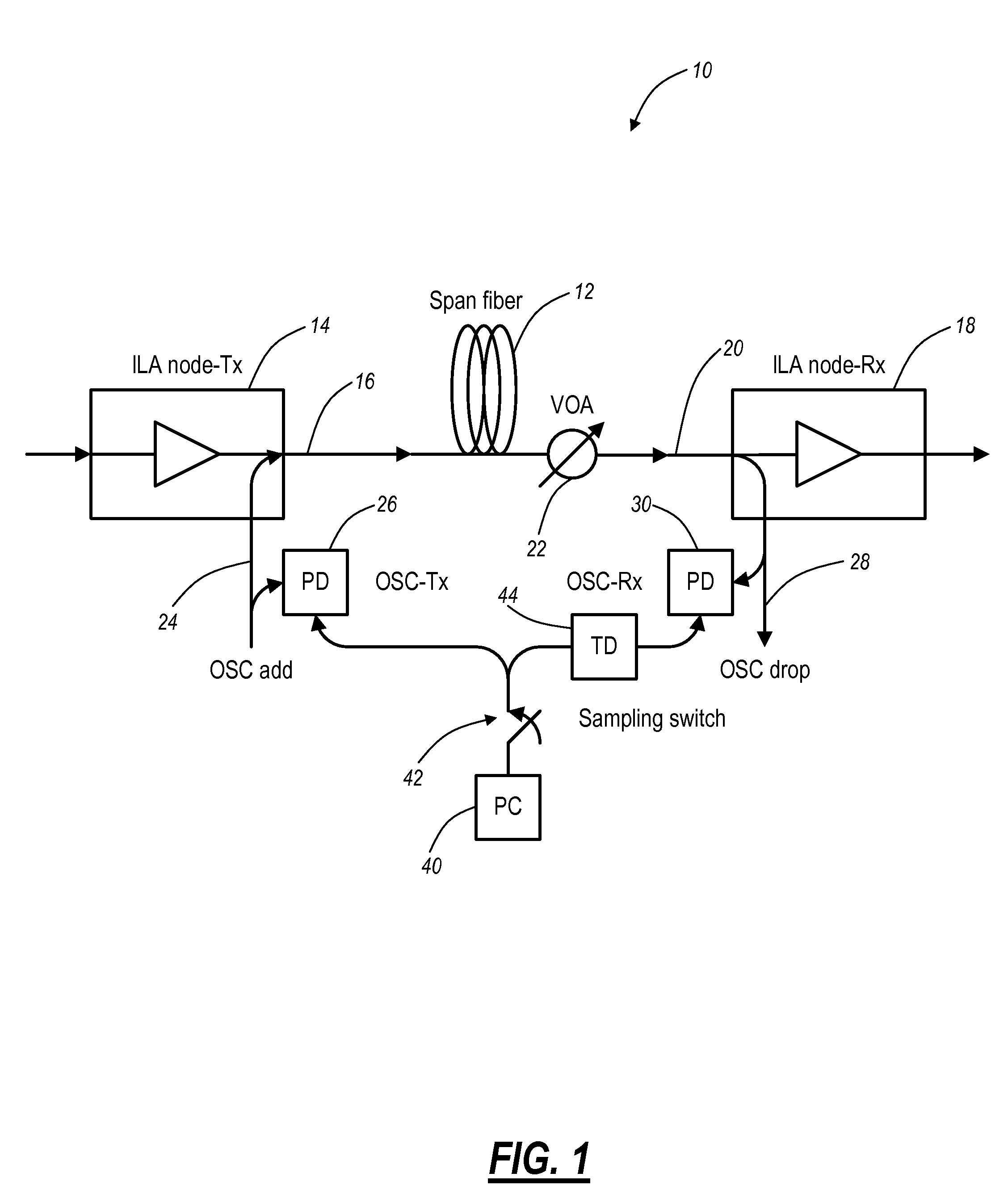
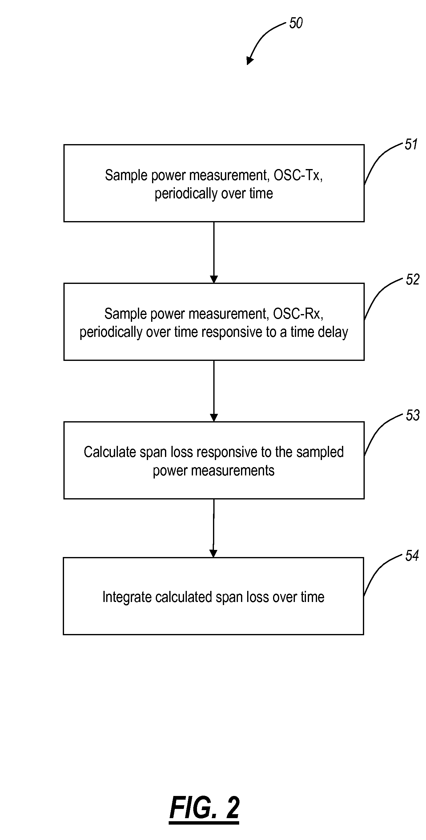
[0024]In various exemplary embodiments, the present invention provides methods and systems for detecting small span loss changes in fiber optic networks. The present invention utilizes existing equipment without additional hardware to provide span loss measurements in a highly accurate manner (i.e., capable of detecting span loss changes of 0.01 dB or 0.03%). In an exemplary embodiment, the present invention utilizes power measurements associated with an optical supervisory channel (OSC) at both ends of a fiber span. These measurements are periodically sampled taking into account propagation time delay along the fiber span. Further, these measurements are integrated or time-averaged to account for temporary fluctuations in the fiber span loss thereby enabling small loss changes to be detected. The present invention can be utilized for intrusion detection (e.g., unwanted fiber taps), fiber degradation detection, and fiber aging performance. The present invention satisfies the criteri...


PUM


Abstract

The present disclosure provides methods and systems for detecting small span loss changes in fiber optic networks. The present invention utilizes existing equipment without additional hardware to provide span loss measurements in a highly accurate manner. In an exemplary embodiment, the present invention utilizes power measurements associated with an optical supervisory channel (OSC) at both ends of a fiber span. These measurements are periodically sampled taking into account propagation delay along the fiber span. Further, these measurements are integrated or time-averaged to account for temporary fluctuations. The present invention can be utilized for intrusion detection (i.e., unwanted fiber taps), fiber degradation, and fiber aging performance. The present invention satisfies the criteria for a feasible (i.e., makes use of current architecture), cost-effective (i.e., does not require additional hardware), and highly accurate solution (i.e., capable of detecting span loss changes of 0.01 dB or 0.03%).

Description

FIELD OF THE INVENTION[0001]The present invention relates generally to optical networking. More particularly, the present invention provides methods and systems for detecting small optical span loss changes (e.g., within an accuracy of 0.01 dB) in fiber optic networks utilizing existing hardware, such as optical supervisory channels (OSCs), photo-detectors, and the like.BACKGROUND OF THE INVENTION[0002]Today's fiber optic networks are highly intelligent, providing the efficient communication of information. The efficiency is largely enabled by the communication between nodes in fiber optic networks. For example, through inter-node communication, channel power can be monitored throughout the network, which allows for automated provisioning, such as channel power offsets at transmitter nodes to compensate for spectral ripple, gain at inline amplifiers nodes to compensate for span loss, and the like. For example, inter-node communication can achieved using a dedicated optical wavelengt...

Claims


Application Information

Patent Timeline
Patent Type & Authority Patents(United States)
IPC IPC(8): H04B10/08
CPCH04B10/0775
Inventor ITO, CHRISFELDMAN, SANDRA
Owner CIENA
Learn More