
Filtering face-piece respirator support structure that has living hinges

a technology of respirator support and facepiece, which is applied in the direction of breathing protection, protective clothing, manufacturing tools, etc., can solve the problems of contaminated air entering the mask interior unfiltered, affecting the effect of airflow, so as to achieve the effect of not causing damag

Inactive Publication Date: 2012-02-21
3M INNOVATIVE PROPERTIES CO
View PDF51 Cites 28 Cited by
  • Summary
  • Abstract
  • Description
  • Claims
  • Application Information

AI Technical Summary

Benefits of technology

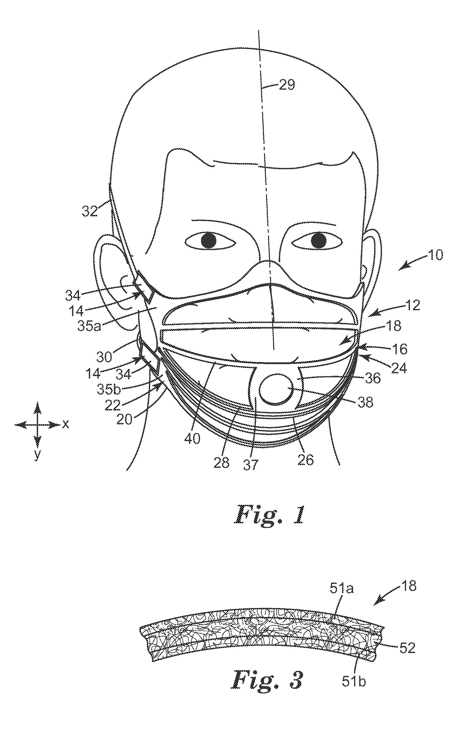
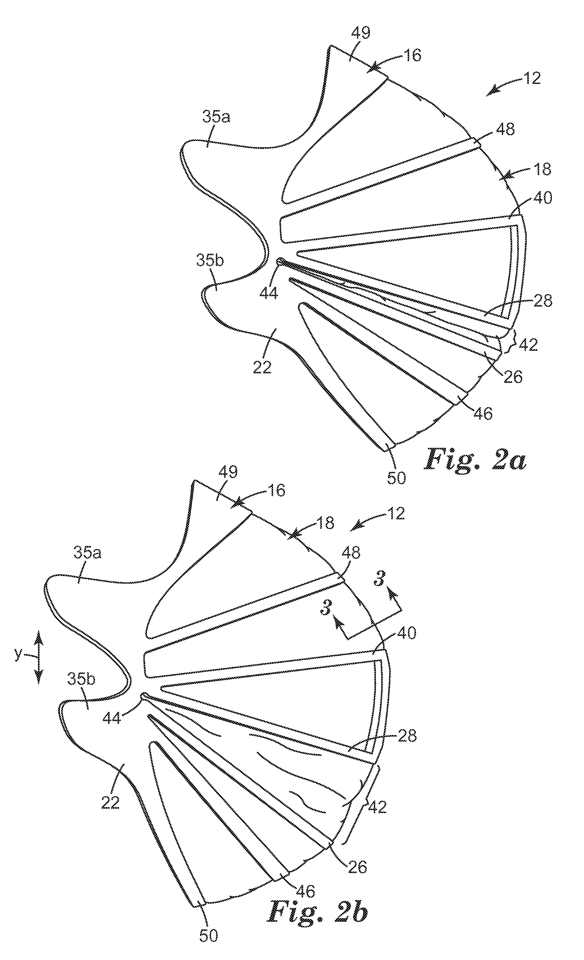
[0011]As indicated above, mask bodies for conventional filtering face-piece respirators have regularly used a support structure that comprised a nonwoven web of thermally bonded fibers or an open-work plastic mesh to support the filtration layer. These conventional support structures were lacking in an ability to dynamically respond to wearer jaw movement. The provision of living hinges in the support structure of a filtering face-piece respirator allows the support structure to better accommodate a person's jaw motion. The ability to accommodate wearer jaw movement in accordance with the present invention can enable the mask body to better remain in its desired position on the wearer's face during use. The provision of living hinges also can allow a single respirator to fit a greater range of face sizes and may alleviate the clamping action on the nose.GLOSSARY
[0030]“living hinge” means a mechanism that allows members that integrally extend therefrom to generally pivot thereabout in a rotational-type manner with such ease that damage is not caused to the members or to the hinge joint under normal use;

Problems solved by technology

The mask bodies that have been designed, however, have generally been non-dynamic structures that do not accommodate the motion of the wearer's jaw.
When the respirator shifts from its desired position on the wearer's face, opportunities may be created for contaminated air to enter the mask interior unfiltered.
In addition, the opening of the jaw tends to pull the mask body downward, causing a clamping action on the nose.
The non-dynamic structure of conventional respirators thus may create uncomfortable conditions for the wearer.
These conventional support structures were lacking in an ability to dynamically respond to wearer jaw movement.

Method used


Image

  • Filtering face-piece respirator support structure that has living hinges
  • Filtering face-piece respirator support structure that has living hinges
  • Filtering face-piece respirator support structure that has living hinges

Examples


examples

Test Methods

1. Stiffness in Flexure Test (SFT)

[0077]The stiffness in flexure of material used to make the support structure was measured according to ASTM D 5342-97 section 12.1 to 12.7. In so doing, six test specimens were cut from a blank film into rectangular pieces that were about 25.4 mm wide by about 70 mm long. The specimens were prepared as described below. Taber V-5 Stiffener tester Model 150-E (from Taber Corporation, 455 Bryant Street, North Tonawanda, N.Y., 14120) was used in 10-100 Taber stiffness unit configurations to measure the test specimens. The Taber Stiffness readings were recorded from the equipment display at the end of the test, and the stiffness in flexure was calculated using the following equation:

[0078]Stiffness⁢⁢in⁢⁢Flexure⁢⁢(Pa)=7,492⁢⁢Ncm4M2⁢(Taber⁢⁢StiffnessWidth*thickness3)[0079]Taber Stiffness=recorded material resistance to bending measured according to ASTM D5342-97 section 12.1 to 12.7.[0080]Width=width of test film specimen in cm, which was 2.54...


PUM

PropertyMeasurementUnit
forceaaaaaaaaaa
forceaaaaaaaaaa
forceaaaaaaaaaa

Abstract

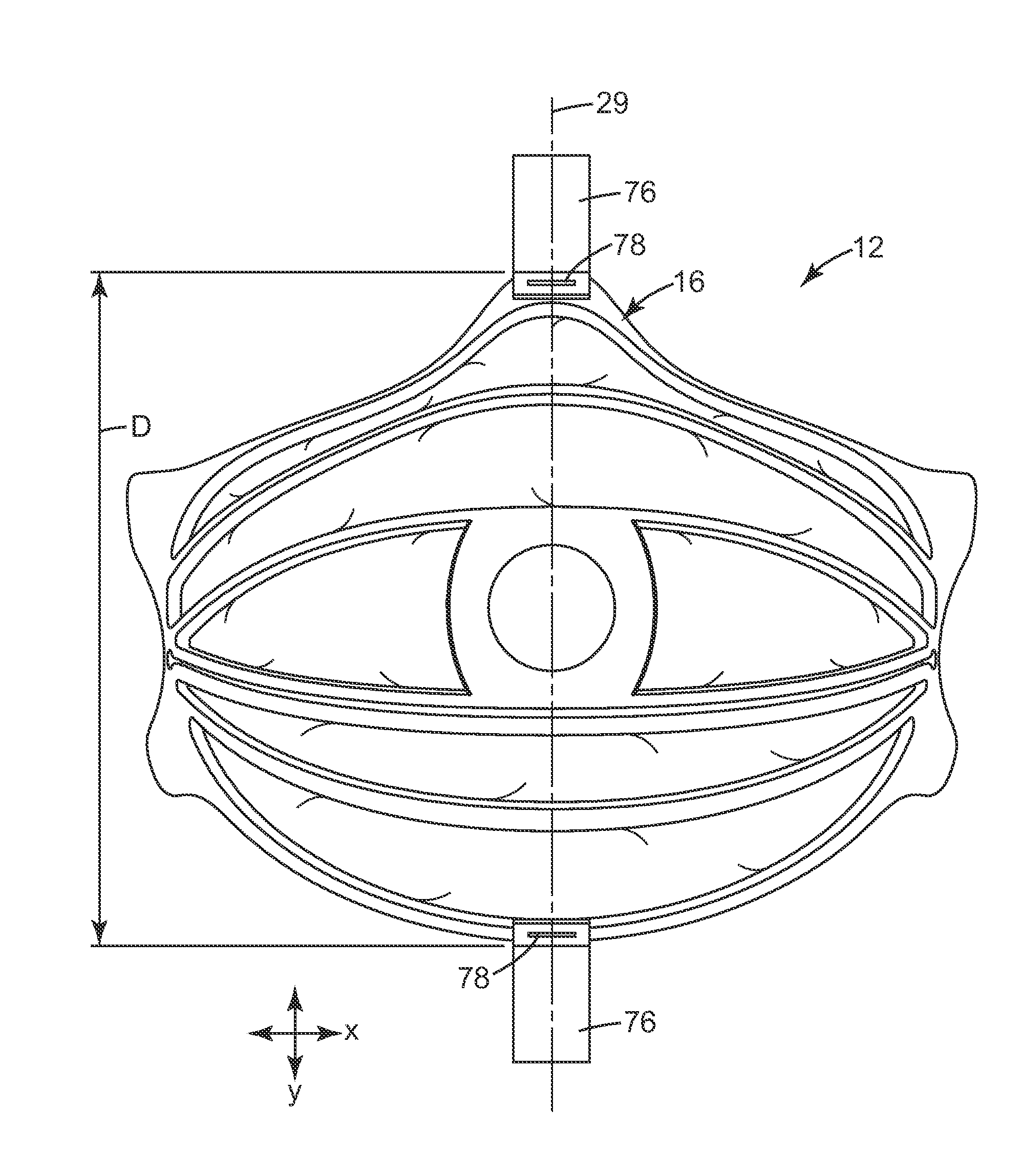
A filtering face-piece respirator 10 that comprises a harness 14 and a mask body 12. The mask body 16 includes a filtering structure 18 and a support structure 16. The support structure 16 has first and second opposing side portions 22, 24 that each include a living hinge 44. The use of living hinges allows the mask body to respond dynamically to wearer jaw movement.

Description

CROSS-REFERENCE TO RELATED APPLICATION[0001]This application claims the benefit of U.S. Provisional Patent Application No. 60 / 974,017, filed Sep. 20, 2007.[0002]The present invention pertains to a respirator that has a mask body that includes a living hinge on each side of its support structure. The living hinges enable the respirator mask body to better accommodate wearer jaw movement. The living hinges also may allow a single mask body to better accommodate various face sizes.BACKGROUND[0003]Respirators are commonly worn over the breathing passages of a person for one of two common purposes: (1) to prevent impurities or contaminants from entering the wearer's breathing track; and (2) to protect other persons or things from being exposed to pathogens and other contaminants exhaled by the wearer. In the first situation, the respirator is worn in an environment where the air contains particles that are harmful to the wearer, for example, in an auto body shop. In the second situation,...

Claims


Application Information

Patent Timeline
Patent Type & Authority Patents(United States)
IPC IPC(8): A62B18/08
CPCA62B23/025Y10T29/49826A41D13/1115A62B18/02A62B18/025
Inventor GEBREWOLD, YONASSKULLEY, THOMAS G.JOHNSON, ERIK J.BEHYMER, LANCE E.DAUGAARD, DWAYNE D.STEPAN, DANIEL J.MARTIN, PHILIP G.
Owner 3M INNOVATIVE PROPERTIES CO
Learn More