Small-hole reinforced fracturing grain and single-surface hoop slit grain combined cutting undermine method

A charge and cutting technology, which is applied in earth drilling, mining equipment, offensive equipment, etc., can solve the problems of low blasthole utilization rate, low energy utilization rate of explosives, poor cutting effect of expansion space, and increased sandwiching effect of surrounding rocks, etc. , to achieve the effects of improving blasthole utilization and explosive energy, increasing damage range, and reducing blasting vibration

Inactive Publication Date: 2020-08-28
ANHUI UNIV OF SCI & TECH +1
View PDF8 Cites 2 Cited by
  • Summary
  • Abstract
  • Description
  • Claims
  • Application Information

AI Technical Summary

Problems solved by technology

The main difficulties faced in cutting and blasting in deep hard rock roadways are as follows: first, the damage range of the traditional charge structure is limited: the hard rock itself is difficult to crack, and the deep ground stress will inhibit rock blasting and cracking; Single surface: only the working surface is used as a free surface, and the inability to provide sufficient expansion space is also the main reason for the poor cutting effect; the third is the clamping effect: the clamping effect of hard rock itself is relatively large, and with the depth of mining increase, the in-situ stress makes the clamping effect of the surrounding rock significantly increase
These reasons make it difficult to obtain a larger cutting cavity during cutting blasting in deep hard rock roadways, which in turn leads to relatively low blasthole utilization and explosive energy utilization in the subsequent blasting process

Method used


Image

  • Small-hole reinforced fracturing grain and single-surface hoop slit grain combined cutting undermine method
  • Small-hole reinforced fracturing grain and single-surface hoop slit grain combined cutting undermine method
  • Small-hole reinforced fracturing grain and single-surface hoop slit grain combined cutting undermine method

Examples


Embodiment 1

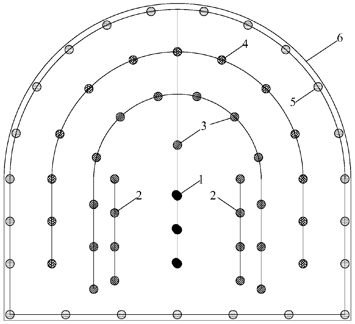
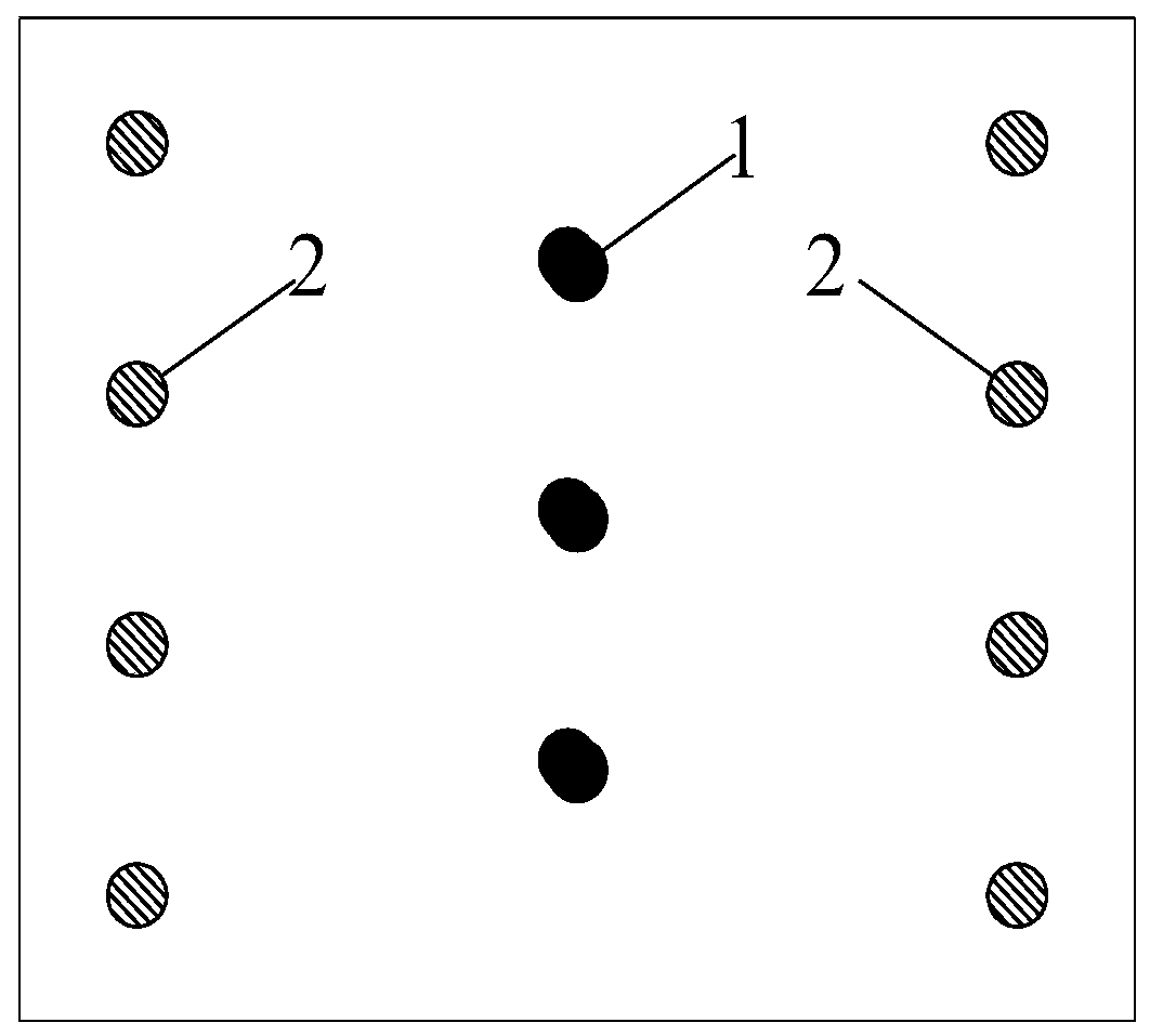
[0063] In the deep underground -800m hard sandstone roadway, the combined cutting method of small hole reinforced fracturing charge and single-sided circumferential slit charge is adopted, including the following steps:

[0064] 1) Drilling: Using a hydraulic drilling rig, a 2.6m long rock drill rod, and a drill bit with a diameter of 42mm, drill a central cut hole 1, wedge cut hole 2, auxiliary hole 3, and caving hole 4 on the roadway section 6 and peripheral holes 5, the central cut hole 1 is located in the middle area of ​​the roadway section 6, the wedge-shaped cut hole 2 is located on the left and right sides of the central cut hole 1, and the auxiliary hole 3 is located on the outside of the wedge-shaped cut hole 2. The above-mentioned caving hole 4 is located outside the auxiliary hole 3, the peripheral hole 5 is located on the outline of the roadway section 6, the depth of the central cut hole 1 and the depth of the wedge-shaped cut hole 2 are 2.5m, and the depth of oth...


PUM


Abstract

The invention discloses a small-hole reinforced fracturing grain and single-surface hoop slit grain combined cutting undermine method, which comprises the following steps of: 1) drilling; 2) charging:enabling central cutting undermine holes to use a decked charge structure and the small-hole reinforced fracturing grain, filling a second-decked small-hole reinforced fracturing grain into the bottom of each central cutting undermine hole, then, immediately filling tap-hole clay of which the length is 400-500 mm, then, filling a first-decked small-hole reinforced fracturing grain, finally, blocking by the tap-hole clay, filling a second-stage single-surface hoop slit grain into wedge-shaped cutting undermine holes, blocking by the tap-hole clay, filling third-decked common explosive in auxiliary holes, blocking by the tap-hole clay, filling four-decked common explosive in caving holes, blocking by the tap-hole clay, filling five-decked common explosive in surrounding holes, and blockingby the tap-hole clay; and 3) blasting. According to the method disclosed by the invention, the volume of a cutting undermine cavity can be enlarged, a free surface is increased, a surrounding rock clamping function is lowered, and a blast hole use ratio and an explosive energy use ratio are improved.

Description

technical field [0001] The invention relates to the technical field of blasting, in particular to a combined cutting method of a small hole reinforced fracturing charge and a single-side circumferential slit charge. Background technique [0002] Cutting in roadway blasting is the key to determine the overall rock-breaking effect and the size of the cycle footage. A reasonable cutting method is conducive to the blasting of the rock mass to form a cavity, and provides a good free surface for the subsequent blasting to achieve a good blasting effect. With the depletion of shallow mineral resources, the development of mineral resources gradually moves to deep, inevitably encountering in-situ stress. The main difficulties faced in cutting and blasting in deep hard rock roadways are as follows: first, the damage range of the traditional charge structure is limited: the hard rock itself is difficult to crack, and the deep ground stress will inhibit rock blasting and cracking; Sin...

Claims


Application Information

Patent Timeline
Patent Type & Authority Applications(China)
IPC IPC(8): F42D1/00F42D1/08F42D3/04F42B3/04F42B3/22E21D9/00
CPCF42D1/00F42D1/08F42D3/04F42B3/04F42B3/22E21D9/006
Inventor 汪海波王梦想吕闹雷小磊马守龙徐颖刘曙杰宗琦吴捷豪程兵丁锋
Owner ANHUI UNIV OF SCI & TECH
Why Eureka
Try Eureka