Controlled blasting construction method of beam nest on vertical shaft wall

A technology of controlled blasting and beam dimples on the shaft wall, which is applied in the field of blasting construction of beam dimples and controlled blasting construction of girder dimples on the shaft wall. It can solve the problems of increased drilling workload, reduced safety performance, and low construction efficiency, and achieves Ensure the effect of blasting forming, reduce the effect of clamping, and improve the effect of construction efficiency

Active Publication Date: 2021-03-02
CHINA UNIV OF MINING & TECH (BEIJING) +1
View PDF5 Cites 2 Cited by
  • Summary
  • Abstract
  • Description
  • Claims
  • Application Information

AI Technical Summary

Problems solved by technology

Due to the time-consuming and complicated process of prefabricating beam nests on the shaft wall, manual excavation of beam nests is often used for beam nest construction in practical engineering applications. However, this method has low construction efficiency and seriously affects the progress of shaft equipment installation.
[0003] At present, the main construction methods of the shaft wall beam sockets are: existing beam sockets, reserved beam sockets and resin anchor beam sockets, among which the construction process of existing beam sockets is relatively complicated, labor-intensive and time-consuming
The reserved formwork for the beam nest is not easy to fix during the pouring of the shaft wall, it is difficult to ensure the accuracy of the position, the construction accuracy cannot be guaranteed, and the utilization rate of the beam nest is poor
The construction of the resin anchor beam socket requires many procedures and high costs, and the construction accuracy of the anchor hole is required to be high
The above three methods all have the limitations of low construction efficiency, long construction time and difficult construction.
[0004] Although the previous patent application CN110196002A mentioned a blasting construction method, it only opened a group of central holes in the main blasting area in the center of the beam nest, that is, the first group of blast holes, and expanded outward to form the second group of blast holes. Holes and the third group of blastholes, the focus of attention is the detonator initiation method of different sections on the top and bottom of each blasthole, so as to form a multi-stage gradient blasting method, and each group of blastholes is connected to form a multi-stage blasting network; Although the directional fracture control blasting charge form of slit charge is also adopted, the slit charge is used in the blast hole in the main blast area, and only conventional directional blasting is achieved; although holes are arranged along the contour area of ​​the beam and nest, but It is a flameproof hole, and the holes are densely arranged, and there is no charge in the hole, which is used to reduce the blasting vibration and reduce the blasting damage
At the same time, the existence of explosion-proof holes will inevitably weaken the blasting effect of the blastholes in the central area on the periphery of the beam nest, resulting in insufficient blasting on the perimeter of the beam nest, which will increase the drilling workload and prolong the construction period of the beam nest. And it needs to be chiseled by manual pick
[0005] When the traditional loose vibration isolation blasting method is used to construct the beam nest, the number of blast holes required is large, the drilling time is long, and it takes a long time to install the wellbore equipment. After the blasting, the beam nest has not yet been formed, and it needs to be expanded and brushed with an artificial jack.
The blasting load has a severe damage effect on the concrete shaft wall, and has a great influence on the strength and stability of the shaft wall structure, which reduces the service life of the shaft and reduces the safety performance

Method used


Image

  • Controlled blasting construction method of beam nest on vertical shaft wall
  • Controlled blasting construction method of beam nest on vertical shaft wall
  • Controlled blasting construction method of beam nest on vertical shaft wall

Examples


Embodiment Construction

[0061] In order to make the purpose, technical solutions and advantages of the embodiments of the present invention more clear, the embodiments of the present invention will be further described in detail below in conjunction with the embodiments and accompanying drawings. Here, the exemplary embodiments and descriptions of the present invention are used to explain the present invention, but not to limit the present invention.

[0062] It is to be understood that the terms "comprising / comprising", "consisting of" or any other variation thereof are intended to cover a non-exclusive inclusion such that a product, apparatus, process or method comprising a set of elements includes not only those elements , and may include other elements not expressly listed, or elements inherent in the product, apparatus, process or method, as required. Without further limitations, an element defined by the phrase "comprising / comprising...", "consisting of... does not exclude the presence of addit...


PUM


Abstract

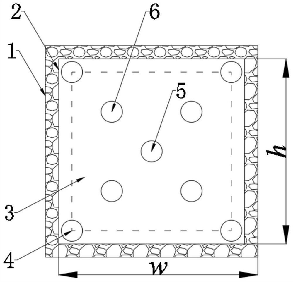
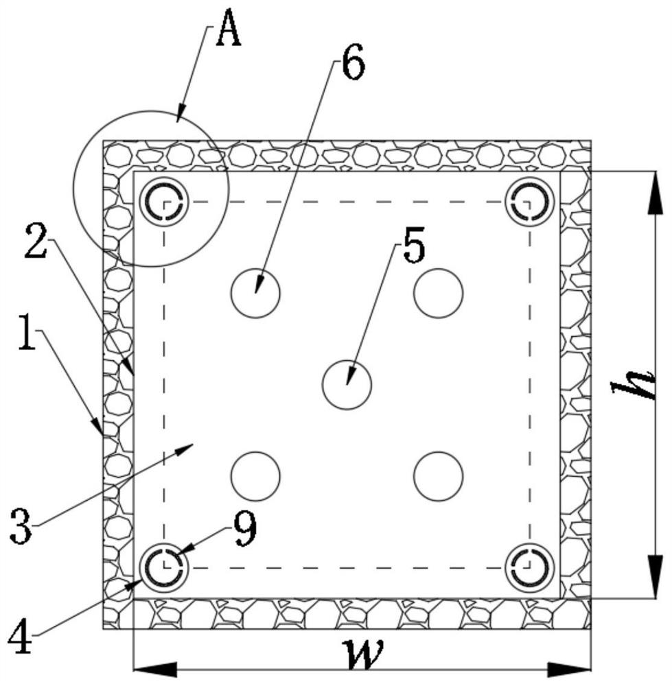
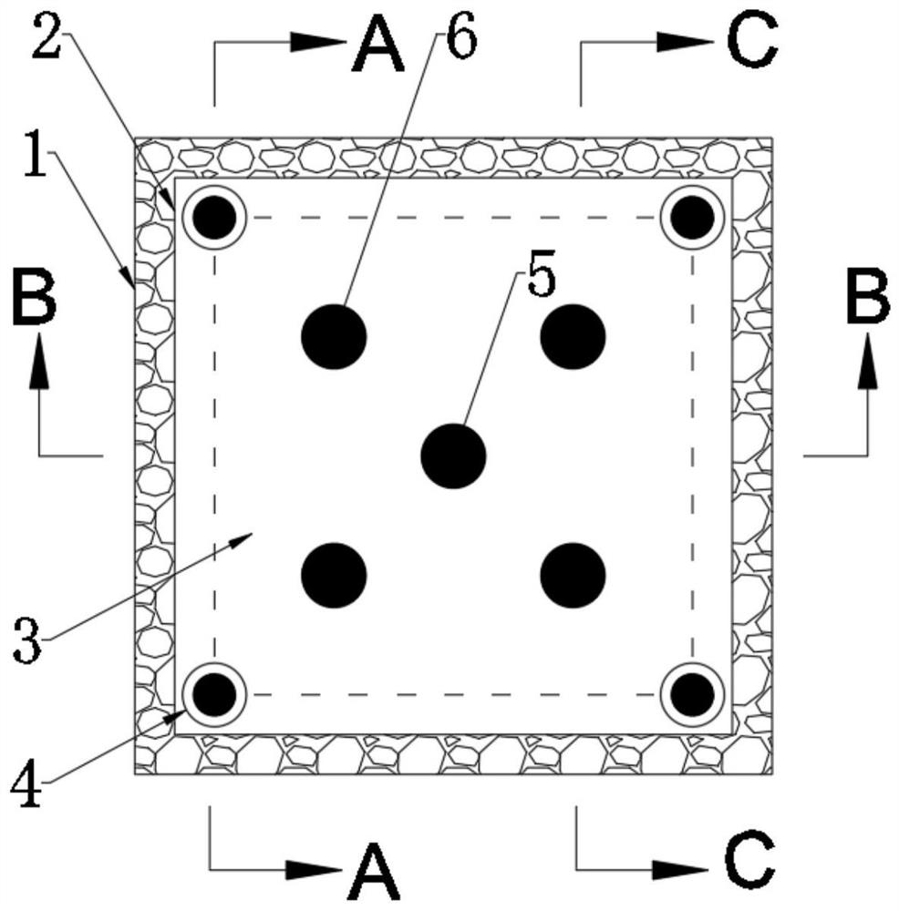
The invention relates to a controlled blasting construction method of a beam nest on a vertical shaft wall. The method comprises the following steps that the beam nest outline boundary is determined on the vertical shaft wall; a set of corner blasthole is arranged and constructed in each corner of the beam nest according to the beam nest outline boundary, a central blasthole is arranged and constructed in the center of the beam nest, and at least one set of auxiliary blasthole is arranged and constructed between each corner blasthole and the central blasthole; 90-degree kerf explosive tubes are arranged in all the corner blastholes, and a first-section explosive and second-section explosives are arranged in the central blasthole and the auxiliary blastholes; and detonating is carried out according to the detonating sequence of corner blasthole explosives, central blasthole top explosives, auxiliary blasthole top explosives, central blasthole bottom explosives and auxiliary blasthole bottom explosives to finish controlled blasting construction of the beam nest. According to the method, 90-degree kerf explosive bags are arranged in the corner blastholes of peripheral holes of the beam nest to form vibration isolation pre-cracks, and a staged and sectioned blasting manner is adopted in a main blasting area, so that safe and efficient controlled blasting of the beam nest on the vertical shaft wall is realized.

Description

technical field [0001] The invention relates to a construction method for a beam nest on a shaft wall of a mine vertical shaft, in particular to a blasting construction method for a beam nest, in particular to a controlled blasting construction method for a beam nest on a shaft wall. Background technique [0002] In the mine construction project, the vertical shaft construction is the throat project of the entire mining area construction, and its construction speed directly determines the progress of the mine area being completed and put into production. Due to the narrow construction space, single free surface, complex maintenance structure, large lithology changes, large water inflow, and high construction safety requirements, the vertical shaft construction speed is greatly limited. As the maintenance structure of the shaft wall, the vertical shaft shaft plays the role of support body and waterproof layer. Its integrity and stability are the direct determinants of the saf...

Claims


Application Information

Patent Timeline
Patent Type & Authority Applications(China)
IPC IPC(8): F42D3/04F42D1/00E21D1/00
CPCF42D3/04F42D1/00E21D1/00
Inventor 杨仁树杨立云赵志伟王秀会李芹涛郑昌达李明辉
Owner CHINA UNIV OF MINING & TECH (BEIJING)
Why Eureka
Try Eureka