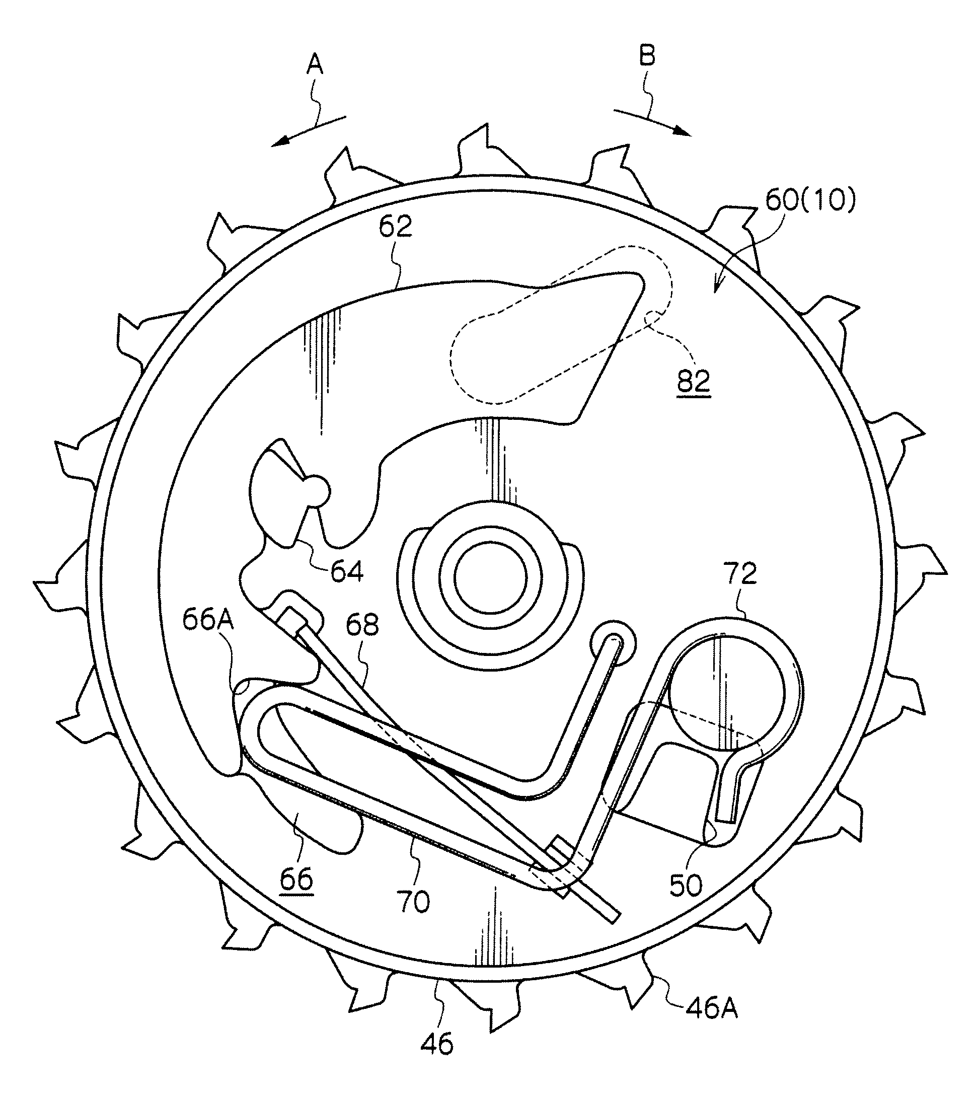
Webbing winder
a winder and webbing technology, applied in the field of webbing winders, can solve the problems of preventing the movement of the restricting member the restricting member cannot reach the restriction position, and the restricting member cannot be moved to the restriction position, so as to achieve the effect of further miniaturization further saving of space, and enhancing the mountability of the rotary member
- Summary
- Abstract
- Description
- Claims
- Application Information
AI Technical Summary
Benefits of technology
Problems solved by technology
Method used
Image
Examples
first exemplary embodiment
[0031]
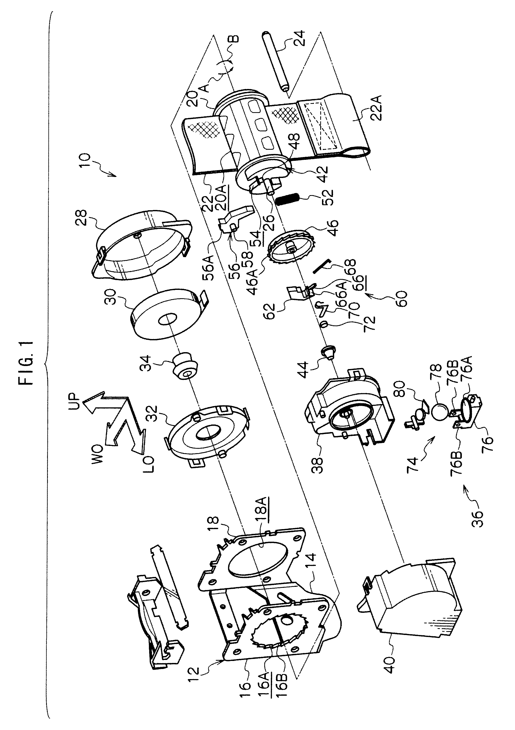
[0032]FIG. 1 is an exploded perspective view showing the entire configuration of a webbing winder 10 in a first exemplary embodiment according to the present invention. In FIG. 1, an arrow LO indicates one side in a lengthwise direction of a vehicle; another arrow WO indicates one side in a widthwise direction of the vehicle; and a further arrow UP indicates an upward direction.
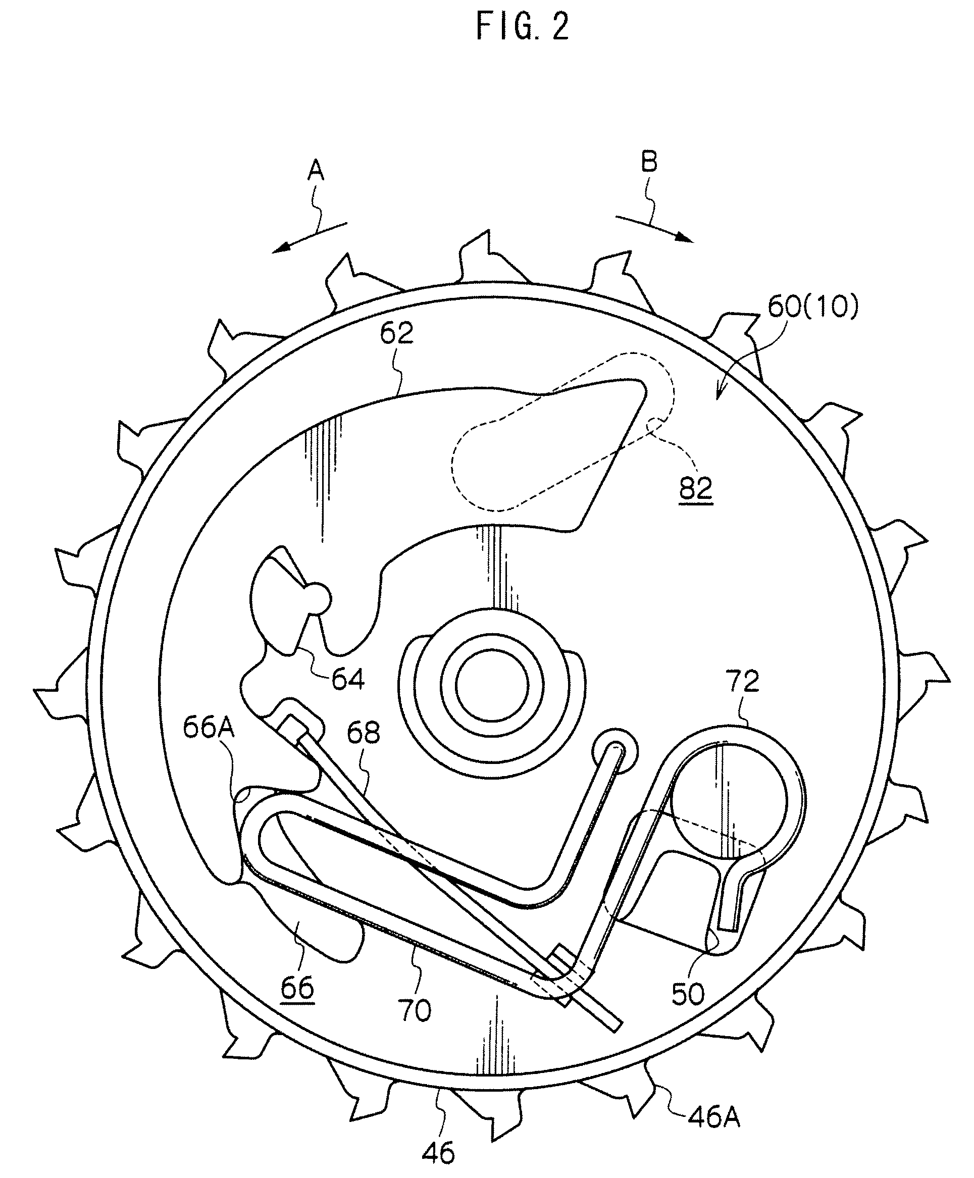
[0033]As shown in FIG. 1, the webbing winder 10 is provided with a frame 12. The frame 12 includes, for example, a back plate 14 disposed substantially vertically in the widthwise direction of the vehicle. The back plate 14 is secured to a chassis in the vicinity of, for example, a lower end of a center pillar of the vehicle via tightening means such as a bolt, so that the webbing winder 10 is installed to the chassis. A leg plate 16 is bent toward the other side in the widthwise direction of the vehicle from one side end in the lengthwise direction of the vehicle of the back plate 14 whereas another le...
second exemplary embodiment
[0069]FIG. 4 is a front view showing essential parts of a webbing winder 100 in a second exemplary embodiment according to the invention.
[0070]The webbing winder 100 is configured in a manner substantially similar to that in the above-described first exemplary embodiment except points below.
[0071]In the webbing winder 100, a rotation detecting mechanism 60 is provided with a W pawl 102 serving as an engaging member (a meshing member) and an inertia mass 104 serving as a rotation detecting member in place of the W pawl 62 in the above-described first exemplary embodiment, wherein the W pawl 102 and the inertia mass 104 are arranged in a radial direction of a V gear 46.
[0072]The W pawl 102 is pivotably supported by a pin 106 formed at the V gear 46 at a position displaced from an axis of a support shaft 26 so as to be able to oscillate within a predetermined range on an axis parallel to the support shaft 26. The W pawl 102 is configured such that its oscillation brings one end thereof...
PUM
 Abstract
Description
Claims
Application Information
 - R&D
- Intellectual Property
- Life Sciences
- Materials
- Tech Scout
- Unparalleled Data Quality
- Higher Quality Content
- 60% Fewer Hallucinations
Browse by: Latest US Patents, China's latest patents, Technical Efficacy Thesaurus, Application Domain, Technology Topic, Popular Technical Reports.
© 2025 PatSnap. All rights reserved.Legal|Privacy policy|Modern Slavery Act Transparency Statement|Sitemap|About US| Contact US: help@patsnap.com


