Apparatus and method for drawing lines

Inactive Publication Date: 2005-02-22
PANASONIC CORP
View PDF9 Cites 5 Cited by
  • Summary
  • Abstract
  • Description
  • Claims
  • Application Information

AI Technical Summary

Benefits of technology

According to the inventive line-drawing method, short lines can b

Problems solved by technology

As is well known in the art, the division operations require high computational costs in the field of digital computations.
That is to say, the hardware cost and the time for performing those operations are

Method used


Image

  • Apparatus and method for drawing lines
  • Apparatus and method for drawing lines
  • Apparatus and method for drawing lines

Examples


Example

Hereinafter, a first embodiment of the present invention will be described with reference to the accompanying drawings.

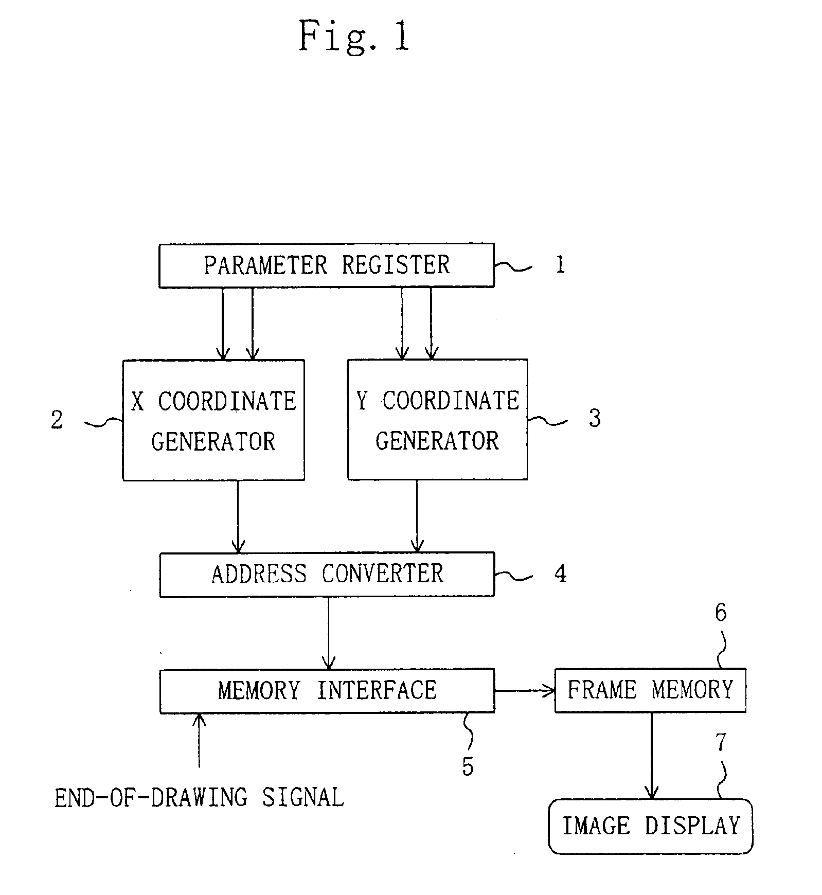
FIG. 1 illustrates a configuration for a line-drawing apparatus of the first embodiment. As shown in FIG. 1, the line-drawing apparatus includes parameter register 1, X and Y coordinate generators 2 and 3, address converter 4, memory interface 5, frame memory 6 and image display 7. Coordinate data, representing an image to be drawn, is temporarily stored on the parameter register 1, X and Y coordinates, included in the coordinate data, are generated by the X and Y coordinate generators 2 and 3, respectively. The address converter 4 converts the two-dimensional coordinate data, generated by the X and Y coordinate generators 2 and 3, into one-dimensional coordinate data, which is passed to, and stored on, the frame memory 6 for storing image frames via the memory interface 5. Then, the coordinate data is eventually presented on the image display 7 such as a liquid cry...

Example

Modified Example of Embodiment 1

Hereinafter, a method using a fixed memory instead of the FIFO memories will be described as a modified example of the first embodiment.

FIG. 14(a) schematically illustrates a fixed memory for storing thereon the data to be passed to the X coordinate calculator 13. The fixed memory 45, i.e., exemplary data storage means as defined in the claims, has its number of stages determined in advance by the longer-side value of a line to be drawn by the line-drawing apparatus. For example, if the longer-side value is 9, then a data storage section with nine stages is needed as shown in FIG. 14(a). If the longer-side value is 17, then a storage section with 17 stages is needed. That is to say, supposing the method using an FIFO memory needs a storage section with a number m of stages (where m is a positive integer), the method using a fixed memory needs a storage section with a number m+1 stages. However, the fixed memory 45 is implementable as a single block, w...

Example

Next, a second embodiment of the present invention will be described with reference to the accompanying drawings.

FIG. 15 illustrates a configuration for a line-drawing apparatus of the second embodiment. In FIG. 15, the same components as those illustrated in FIG. 1 will be identified by the same reference numerals and the description thereof will be omitted herein. As shown in FIG. 15, this apparatus further includes a color information generator 8, which has a similar configuration to that of the X and Y coordinate generators 2 and 3, between the parameter register 1 and the memory interface 5.

The line-drawing apparatus of the second embodiment can perform color interpolation on a line connecting start and end points where color information is added to the coordinate data representing the line including the start and end points.

Hereinafter, it will be described how the line-drawing apparatus with such a configuration operates.

In FIG. 15, first, start and end point coordinate data,...


PUM


Abstract

An inventive line-drawing apparatus draws a line that connects a start point to an end point. The start and end points are both presented on a display and represented by mutually different sets of coordinates. The apparatus includes first and second FIFO memories, an adder and a shifter. Each of the first and second FIFO memories accepts a plurality of input coordinate data and sequentially outputs one of these data after another on a first in, first out basis. The adder receives and adds together the respective coordinate data output from the first and second memories and outputs added data. And the shifter divides the added data by two and outputs divided data. The coordinate data output from the first and second memories are input to the first memory. The divided data is input from the shifter to the second memory. The line connecting the start and end points together is drawn on the display in accordance with the divided data output from the shifter.

Description

BACKGROUND OF THE INVENTIONThe present invention generally relates to a graphics processor for drawing lines as a graphic image on a display device, for example, and more particularly relates to an apparatus that can draw relatively short lines in a shorter amount of time.Thanks to remarkable progress of computer graphics technologies, the capabilities of graphics processors, such as the quantities of data processable per unit time, have tremendously improved. Under the circumstances such as these, the need for drawing an image at an even higher resolution goes on increasing day after day. Typical applications the computer graphics technologies have ever found include computer-aided design (CAD), computer-aided engineering (CAE) and computer games. Recently, however, those technologies have expanded their applications to presentation of maps on the display of a car navigation system using a global positioning system (GPS).A car navigation system, in particular, often needs to presen...

Claims


Application Information

Patent Timeline
IPC IPC(8): G06T11/20
CPCG06T11/203
Inventor KISHI, TETSUJI
Owner PANASONIC CORP
Why Eureka
Try Eureka