RF antenna system having low-power requirements for RFID tag communication

a technology of rf antenna and tag communication, which is applied in the field of radio frequency identification (rfid) tag communication, can solve the problems of adverse effects of rfid readers on items, and achieve the effect of reducing power requirements for use in rfid communication

Inactive Publication Date: 2012-02-21
THE UNITED STATES OF AMERICA AS REPRESENTED BY THE SECRETARY OF THE NAVY
View PDF16 Cites 14 Cited by
  • Summary
  • Abstract
  • Description
  • Claims
  • Application Information

AI Technical Summary

Benefits of technology

[0007]Still another object of the present invention is to provide an RF antenna system that has reduced power requirements for use in RFID communication.

Problems solved by technology

Unfortunately, if the RFID-tagged item is sensitive to electromagnetic radiation (EM), the item could be adversely affected by the RFID reader.
In terms of EM sensitive ordnance or chemicals, this situation could result in a catastrophe.

Method used


Image

  • RF antenna system having low-power requirements for RFID tag communication
  • RF antenna system having low-power requirements for RFID tag communication

Examples


Embodiment Construction

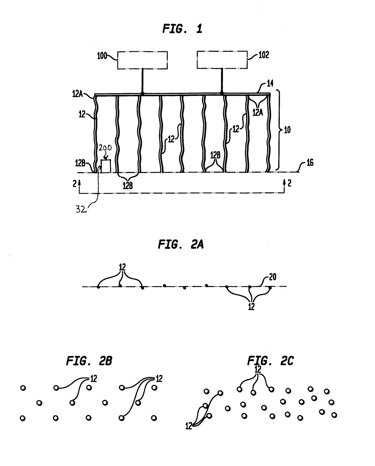
[0018]Referring now to the drawings and more particularly to FIG. 1, an RF antenna system in accordance with the present invention is shown and is referenced generally by numeral 10. As will be explained further below, RF antenna system 10 is specifically designed for use in the field of RFID tag communication to include the activation or excitation of an RFID tag 32 (not shown in detail) and / or the detection or reading of RF signals produced by an activated RFID tag. Accordingly, RF antenna system 10 will have one or both of an RF source 100 and RFID reader 102 coupled thereto as would be understood in the art. RF source 100 and RFID reader 102 could be separate components or could be incorporated into a single device. Thus, the particular configurations of RF source 100 and / or RFID reader 102 are not limitations of the present invention.

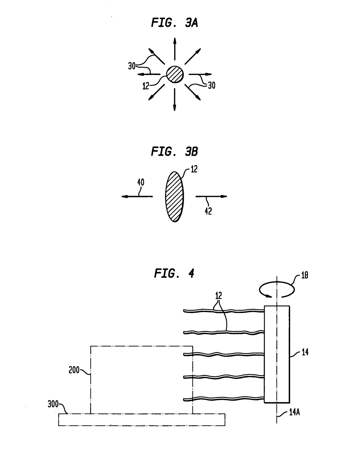
[0019]In general, RF antenna system 10 includes a plurality of flexible wire antennas 12 and a common terminal 14. More specifically, each of wire...


PUM


Abstract

An RF antenna system for RFID tag communication includes a terminal and wire antennas extending therefrom. Each wire antenna has a first end electrically coupled to the terminal and a second end that is unencumbered. At least a portion of each wire antenna to include the second end thereof is flexible in at least one direction so that an RFID tag of an RFID-tagged object contacts at least one of the wire antennas.

Description

ORIGIN OF THE INVENTION[0001]The invention described herein was made in the performance of official duties by an employee of the Department of the Navy and may be manufactured, used, licensed by or for the Government for any governmental purpose without payment of any royalties thereon.FIELD OF THE INVENTION[0002]The invention relates generally to “radio frequency identification” (RFID) tag communication, and more particularly to an RF antenna system that does not need much power to communicate with RFID tags.BACKGROUND OF THE INVENTION[0003]Radio frequency identification (RFID) “tags” are used in a variety of commercial and government applications to provide the means to securely identify an object to which a tag is affixed. Briefly and as is known in the art, RFID tags are powerless passive devices that are “activated” in the presence of a radio frequency (RF) electromagnetic wave. An activated RFID tag resonates to thereby produce a unique wireless signal that can be read / decoded...

Claims


Application Information

Patent Timeline
Patent Type & Authority Patents(United States)
IPC IPC(8): H01Q1/12H01Q21/00G06K19/077
CPCG06K7/10336H01Q1/2216H01Q9/44
Inventor ARMSTRONG, LINCOLN
Owner THE UNITED STATES OF AMERICA AS REPRESENTED BY THE SECRETARY OF THE NAVY
Why Eureka
Try Eureka