

Method and apparatus for magnetic character recognition
a magnetic character and recognition method technology, applied in the field of magnetic character recognition methods and apparatuses, can solve the problems of false recognition, poor printing of magnetic ink, and impaired accuracy of magnetic character recognition, and achieve high accuracy, high coincidence, and high comparison
- Summary
- Abstract
- Description
- Claims
- Application Information
AI Technical Summary
Benefits of technology
Problems solved by technology
Method used
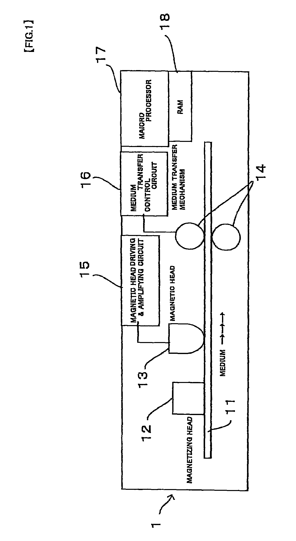
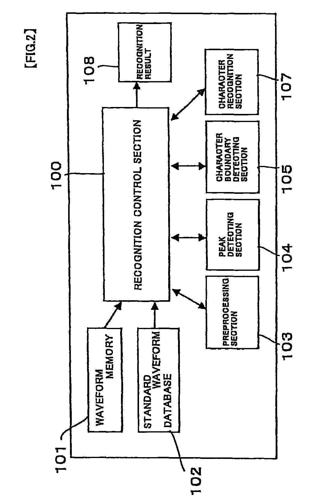
Image

Examples
first embodiment
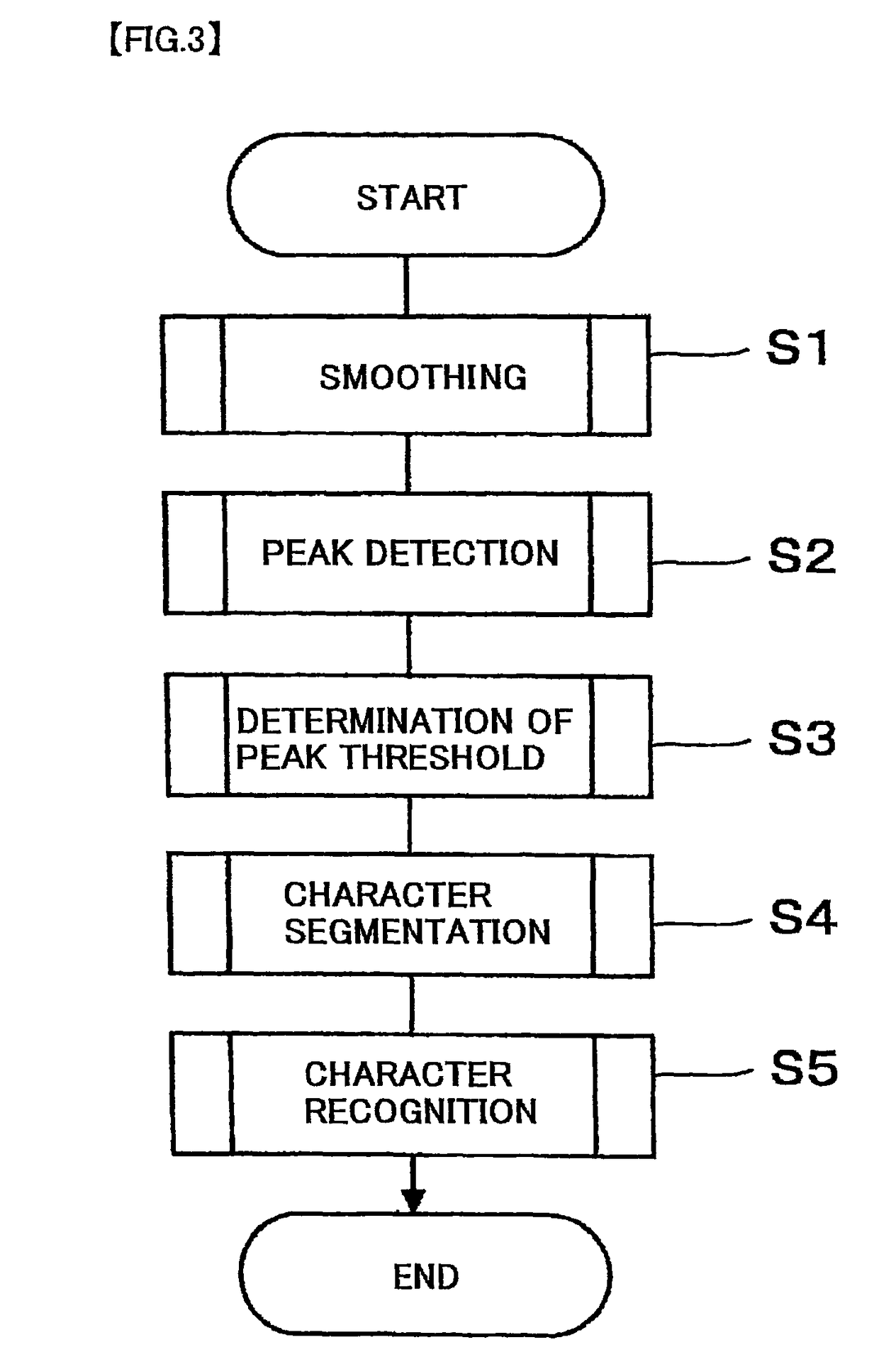
[0086]Subsequently, character recognition is carried out (Step S5 in FIG. 3).
[0087]FIG. 7A is a flowchart showing a detailed workflow of the character recognition (Step S5) described in the flowchart of FIG. 3. Meanwhile, FIG. 8 is an example of a line of magnetic characters printed on a medium such as a check. The magnetic pattern is read in a direction from the right to the left in FIG. 8. The waveforms of magnetic regeneration signals read in such a manner are processed through the steps of the character segmentation described above. As a result, array data of the distances between neighboring two peaks shown below in “(Table 1)” is acquired (Step S31).
[0088]
TABLE 16543211D16D15D14D13D12D112D26D25D24D23D22D213D36D35D34D33D32D31.....................lDi6Di5Di4Di3Di2Di1.....................nDn6Dn5Dn4Dn3Dn2Dn1
[0089]Subsequently, for each character, the array data of the distances between neighboring two peaks is sequentially compared with each of an array data of a template (Standard...
second embodiment
[0101]Character recognition according to a second embodiment is described below next. Being provided with operations from Step S37 through Step S41 before those from Step S31 through Step S36 described above, the second embodiment ensures the character recognition with high accuracy even when there exists a low level of peak output in the regeneration waveform due to a void and / or waveform deformation due to a quasi peak.
Subsequently, the character recognition is carried out (Step S5 in FIG. 3).
[0102]FIG. 7B is a flowchart showing a detailed workflow of the character recognition (Step S5) described in the flowchart of FIG. 3. Meanwhile, FIG. 8 is an example of a line of magnetic characters printed on a medium such as a check. The magnetic pattern is read in a direction from the right to the left in FIG. 8. The waveforms of magnetic regeneration signals read in such a manner are processed through the steps of the character segmentation described above. As a result, array data of the ...
PUM
 Abstract
Description
Claims
Application Information