

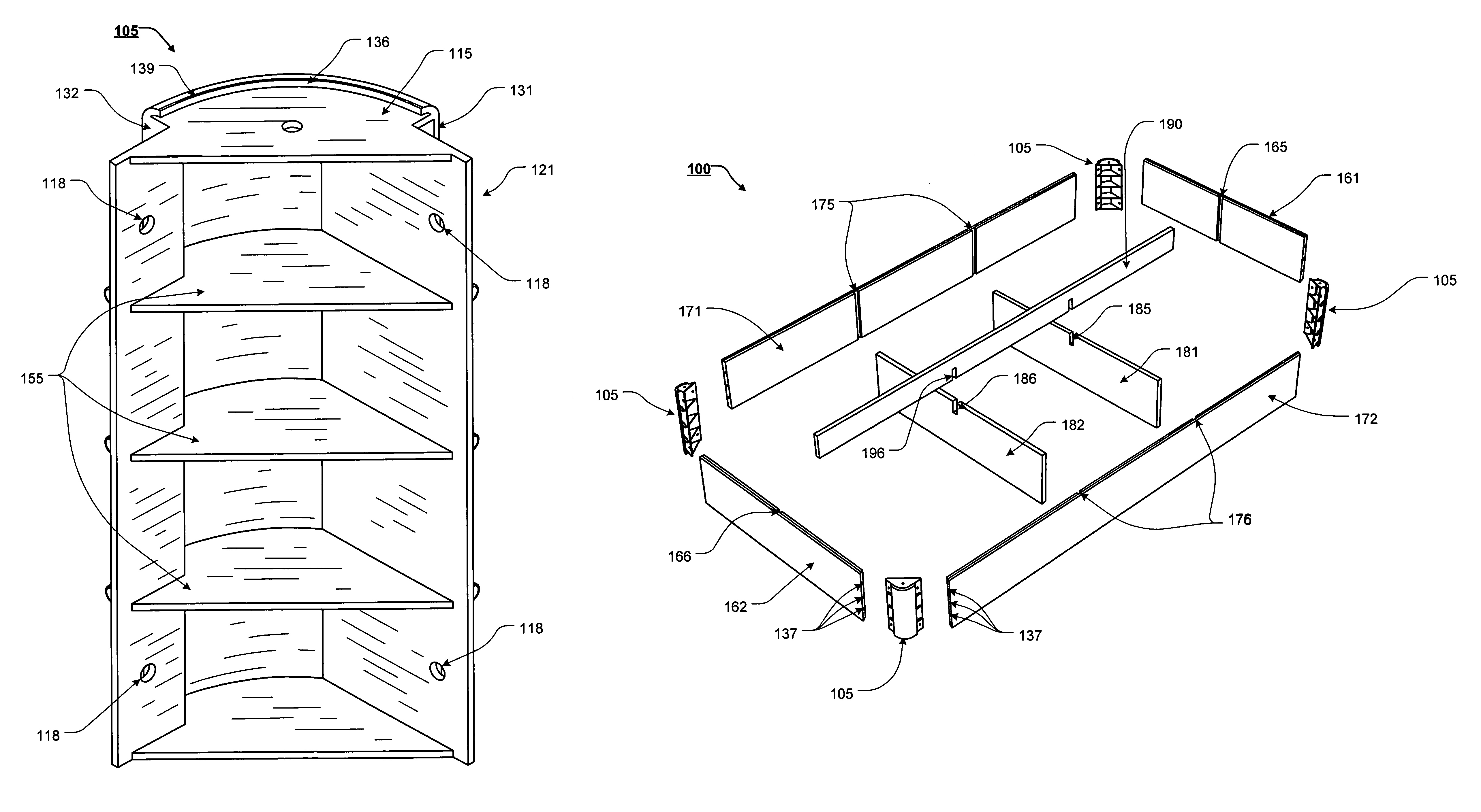
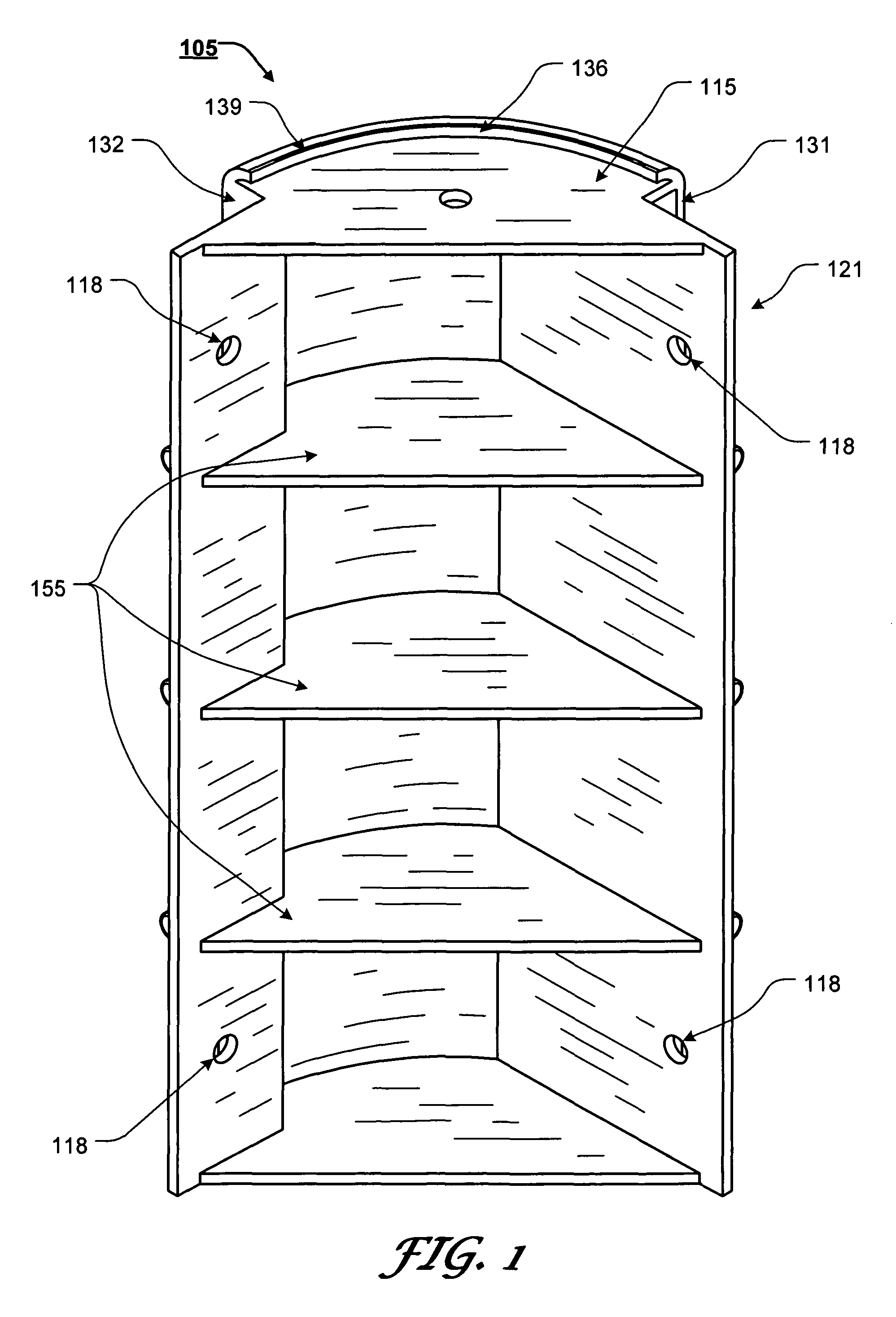
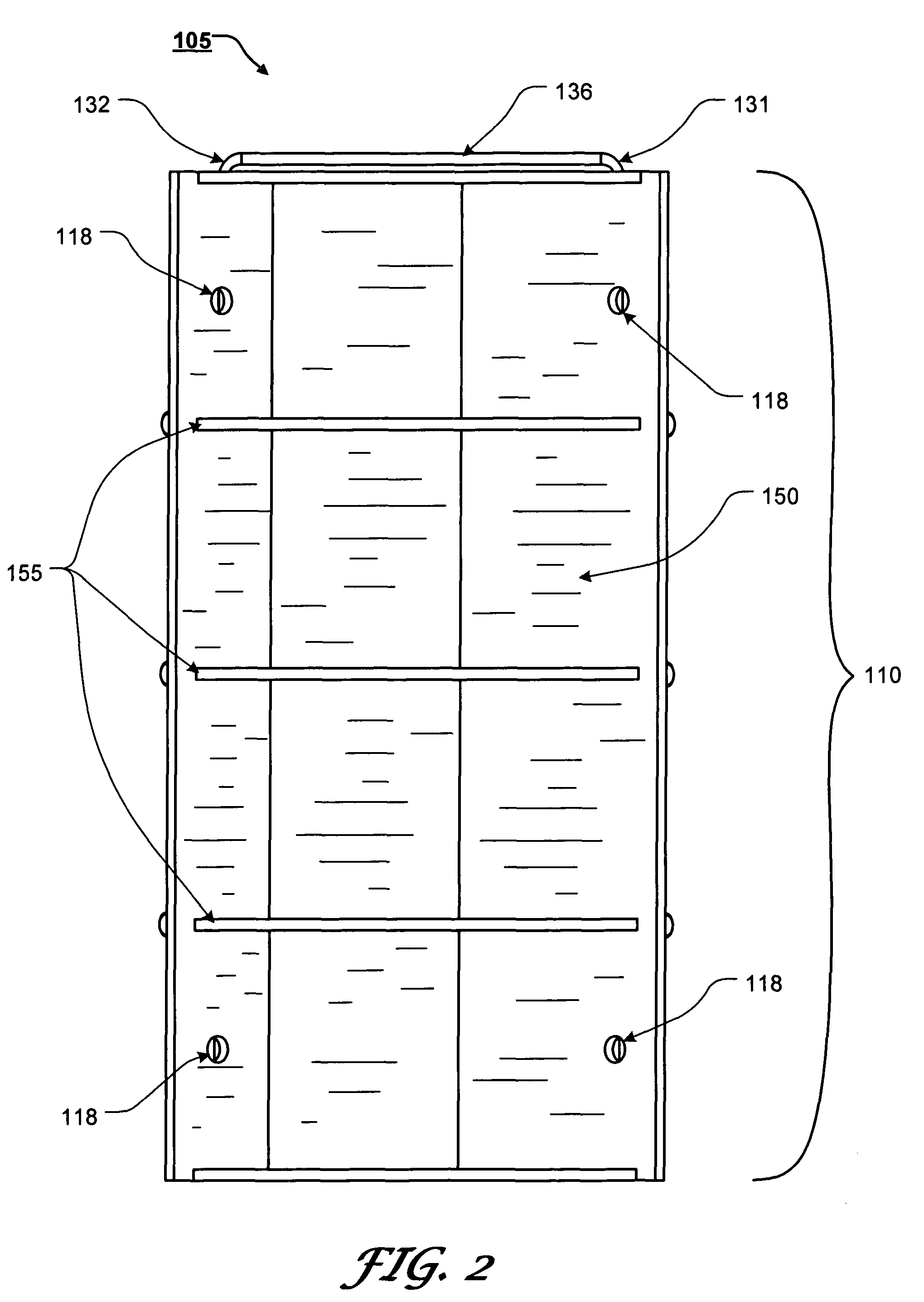
Mattress foundation corner connector and assembly method
a mattress foundation and corner connector technology, applied in the direction of rod connections, beds, sofas, etc., can solve the problems of requiring many components and tools, requiring relatively skilled workers, and constructing mattress foundations using known methods, and achieves the effect of less expensive manufacturing and improved design
- Summary
- Abstract
- Description
- Claims
- Application Information
AI Technical Summary
Benefits of technology
Problems solved by technology
Method used
Image

Examples
Embodiment Construction
[0073]For simplicity and clarification, the design factors and operating principles of the mattress foundation corner connectors and mattress foundation assemblies according to this invention are explained with reference to various exemplary embodiments of mattress foundation corner connectors and / or mattress foundation assemblies according to this invention. The basic explanation of the design factors and operating principles of the mattress foundation corner connectors and mattress foundation assemblies is applicable for the understanding, design, and operation of the mattress foundation corner connectors and mattress foundation assemblies of this invention. It should be appreciated that the mattress foundation corner connectors and / or the mattress foundation assemblies can be adapted to many applications where a simplified corner connector and / or a foundation assembly is needed.
[0074]It should also be appreciated that the terms “mattress foundation”, “mattress foundation assembly...
PUM
 Abstract
Description
Claims
Application Information