Piston and cylinder unit

a cylinder unit and piston technology, applied in the direction of mechanical devices, manufacturing tools, couplings, etc., can solve the problems of increasing the structural length of the piston region, the need for a comparatively complicated hardening method, and the inability to apply high moments during assembly and disassembly without special tools, so as to simplify assembly and disassembly of the unit, the effect of high tightening moments

Active Publication Date: 2012-02-28
HYCO PACOMA
View PDF12 Cites 8 Cited by
  • Summary
  • Abstract
  • Description
  • Claims
  • Application Information

AI Technical Summary

Benefits of technology

[0012]The novel piston and cylinder unit can be mounted without having to apply a high tightening moment. This makes it possible to mount and dismount the piston and cylinder unit by hand. The required means for preventing undesired rotational movement of the piston which has been screwed on the piston rod is realized in a different way compared to the prior art. The new design is inexpensive and easy to be serviced.
[0029]The threads by which the piston is connected to the piston rod and by which the securing element is connected to the piston rod by screwing are designed and arranged to be opposite threads. Preferably, the piston and the piston rod are connected by a left-handed thread and the securing element and the piston rod are connected by a right-handed thread. This simplifies availability of a securing element and handling since a user, for example, when detaching the securing element, expects a normal right-handed thread. However, the arrangement may also be vice versa.

Problems solved by technology

Both above described known arrangements for fixing a piston using a high tightening moment have the following drawbacks: It is not possible to apply the high moments during assembly and disassembly without special tools.
Additional components for preventing unintended rotational movement are required, and they lead to the structural length in the region of the piston being increased.
They contact each other and thus need to be hardened in a comparatively complicated way.
Such piston connections are complicated in manufacture, and they are not easy to be serviced.
The known piston and cylinder unit does not teach any means for preventing rotational movement of the piston with respect to the piston rod, and it also does not disclose a design which is safe and easy to be serviced.
These chips result in undesired soiling.
Fixing the piston is complicated and causes high costs due to the need for manufacturing these elements.

Method used


Image

  • Piston and cylinder unit
  • Piston and cylinder unit
  • Piston and cylinder unit

Examples


Embodiment Construction

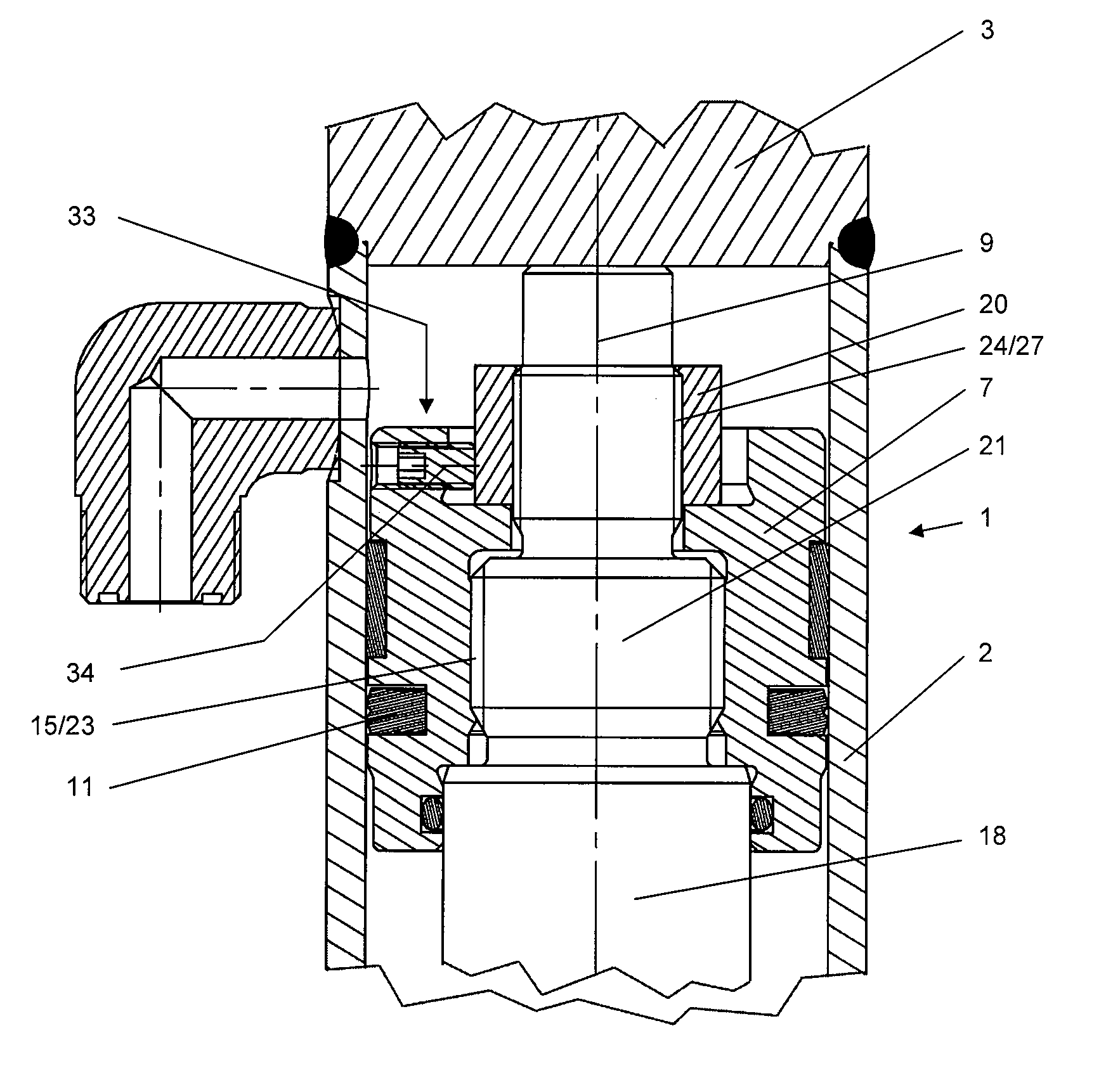
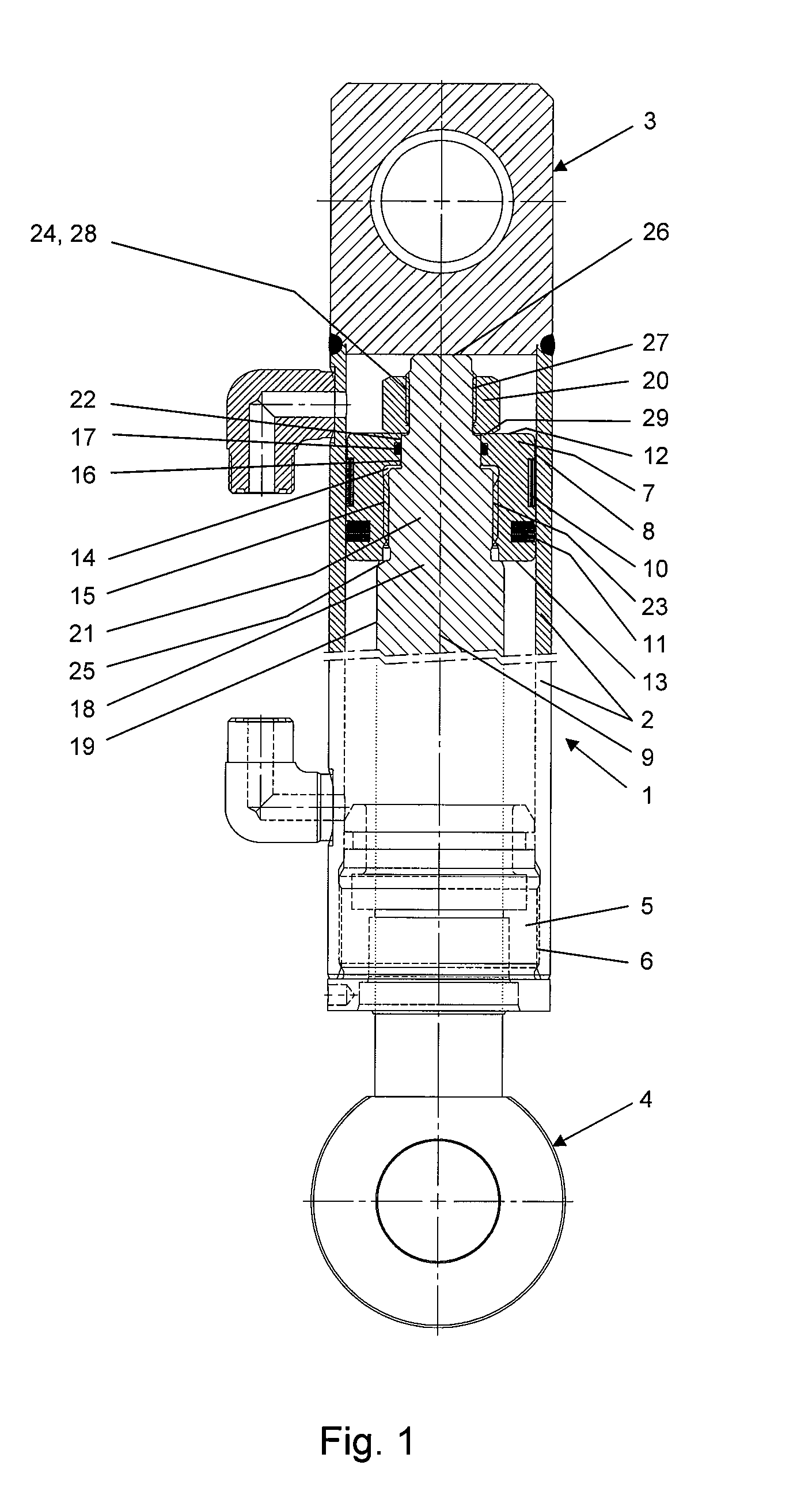
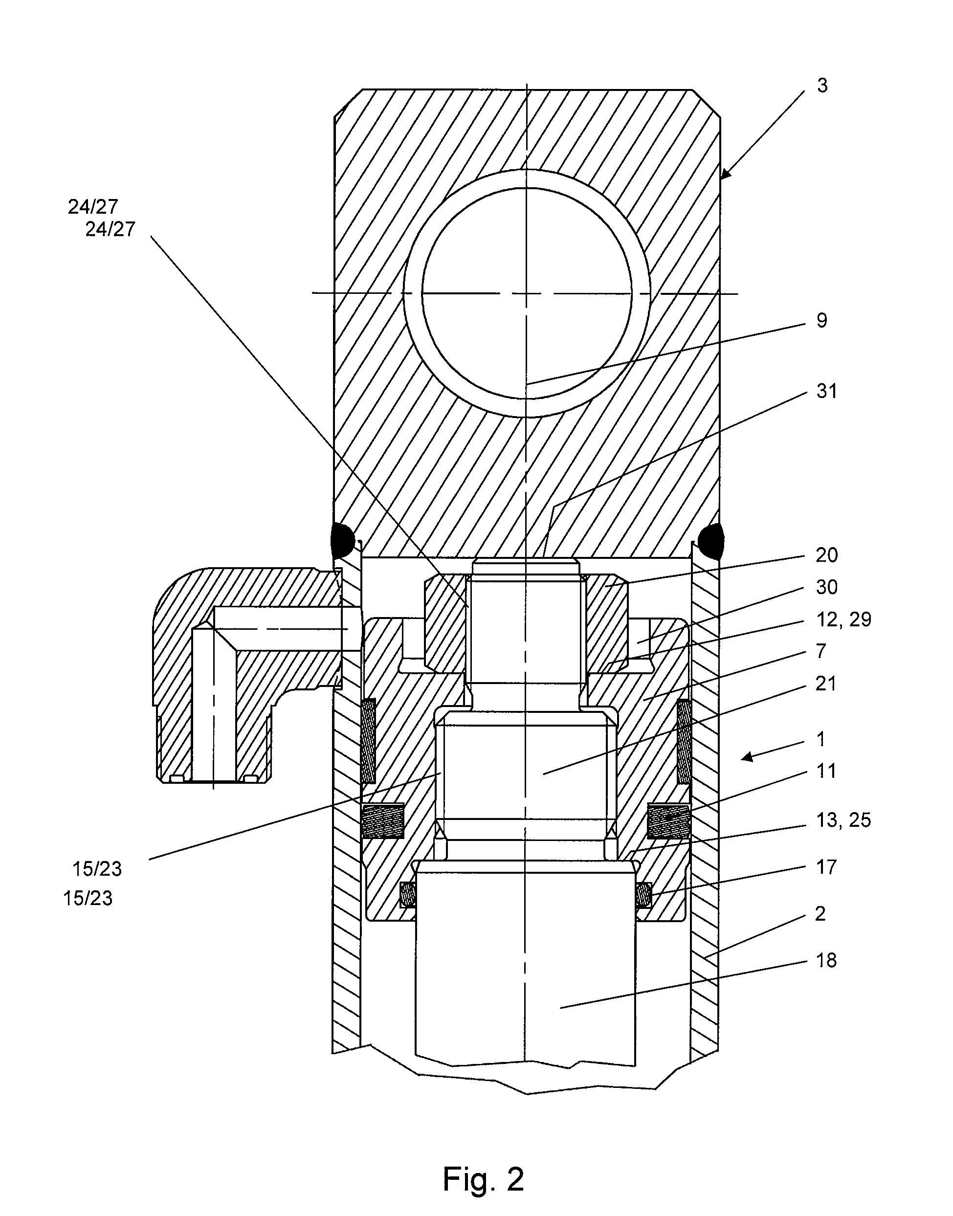
[0039]The novel piston and cylinder unit 1 illustrated in FIG. 1 includes a cylinder housing 2 having a tubular design and at its one end being connected to a bearing 3. A bearing 4 is arranged at the other end of the piston and cylinder unit 1. A guiding bush 5 being connected to the cylinder housing 2 by a thread is located at the side of the cylinder housing 2 facing the bearing 4. The guiding bush 5 is connected to the cylinder housing 2 by a thread 6.

[0040]A piston 7 is slidingly and sealingly arranged in the cylinder housing 2 in a way to be movable. The piston 7 has an outer surface 8 which is designed to be cylindrical. The piston 7 has an axis 9 which is arranged to be concentric to the surface 8 and to coincide with the axes of the piston and cylinder unit 1. Elements for guiding and sealing are arranged on the outer surface 8 of the piston 7. In this case, these elements are a guiding band 10 and a dynamic seal 11. The piston 7 has a first stop surface 12 and a second sto...


PUM


Abstract

A piston and cylinder unit (1) includes a cylinder housing (2), a piston (7), a piston rod (18) and a securing element (20). The piston (7) includes an opening (13), at least one piston seal (11) and an inner thread (15) being located in the opening (13). The piston rod (18) has an axis (9) and includes a protrusion (21), an outer thread (23) and a second thread (27). The outer thread (23) is located on the protrusion (21). The second thread (27) is located at the piston rod (18). The piston (7) and the piston rod (18) are connected by the inner thread (15) and the outer thread (23). The securing element (20) is designed and arranged to substantially extend in the direction of the axis (9). The securing element (20) includes a thread (24), the securing element (20) and the piston rod (18) being connected by the thread (24) of the securing element (20) and the second thread (27) of the piston rod (18). The securing element (20) is designed and arranged to be active in an axial direction in a way to prevent rotational movement of the piston (7) in a loosening direction. The threads (15, 23) of the piston (7) and of the piston rod (18) are designed and arranged to be operated in a direction opposite to the threads (24, 27) of the securing element (20) and the piston rod (21).

Description

CROSS REFERENCE TO RELATED APPLICATIONS[0001]This application claims priority to co-pending German Patent Application No. DE 10 2007 037 760.8 entitled “Kolben / Zylinder-Einheit mit einem Zylindergehäuse, einem Kolben und einer Kolbenstange”, filed Aug. 10, 2007.FIELD OF THE INVENTION[0002]The present invention generally relates to a piston and cylinder unit. More particularly, the present invention relates to a piston and cylinder unit including a cylinder housing, a piston, a piston rod and a securing element.BACKGROUND OF THE INVENTION[0003]A piston and cylinder unit is known from German patent number DE 101 56 504 C1 corresponding to U.S. Pat. No. 6,837,144 B2. The known piston and cylinder unit includes a cylinder housing, a piston including an opening and a piston rod having a common axis. The piston includes a piston seal and a guiding element. The piston with its inner thread being located in the opening is connected to the outer thread of a protrusion of the piston rod witho...

Claims


Application Information

Patent Timeline
Patent Type & Authority Patents(United States)
IPC IPC(8): F16J1/12
CPCF15B15/1447Y10T403/56
Inventor HERWIG, KARL-WILHELM
Owner HYCO PACOMA
Why Eureka
Try Eureka