Vehicle seat

a technology for vehicles and seats, applied in the field of vehicles seats, can solve the problems of increasing manufacturing costs and increasing weight, and achieve the effects of reducing manufacturing costs, facilitating movement, and facilitating retraction

Active Publication Date: 2012-02-28
TOYOTA BOSHOKU KK +1
View PDF25 Cites 19 Cited by
  • Summary
  • Abstract
  • Description
  • Claims
  • Application Information

AI Technical Summary

Benefits of technology

[0009]According to this embodiment, the seat can be switched from the use condition to the retracted condition while the seat back is rotated forwardly (i.e., while the seat is folded). Therefore, the seat can be directly retracted in the floor by utilizing an operational force for rotating the seat back and the gravitational force. That is, the seat can be switched from the use condition to the retracted condition in one operation. In addition, the reclining mechanism can be automatically released or unlocked without operating the operating member. Therefore, a force required to operate the operating member can be reduced.
[0011]According to this embodiment, the seat cushion is supported on the floor by a parallel linkage that is composed of the retracting link and the auxiliary link. Therefore, the seat can be reliably moved along a highly stabilized trajectory when the seat is moved from the use condition to the retracted condition. As a result, the operational force can be effectively used, so that the seat can be smoothly retracted.
[0012]In a further embodiment, a vehicle seat that can be switched between a use condition and a nonuse condition may include a first and second members that can rotate relative to each other when the seat is switched between the use condition and the retracted condition, and a torsion spring. The torsion spring is arranged and constructed to generate biasing forces in the rotational directions of the first and second members, so that the biasing forces can assist the relative rotation of the first and second members when the seat is in the use condition and the nonuse condition. The torsion spring is arranged and constructed such that the directions of the biasing forces thereof can be changed during the relative rotation of the first and second members.

Problems solved by technology

This may lead to increased manufacturing cost and increased weight.

Method used


Image

  • Vehicle seat
  • Vehicle seat
  • Vehicle seat

Examples


first embodiment

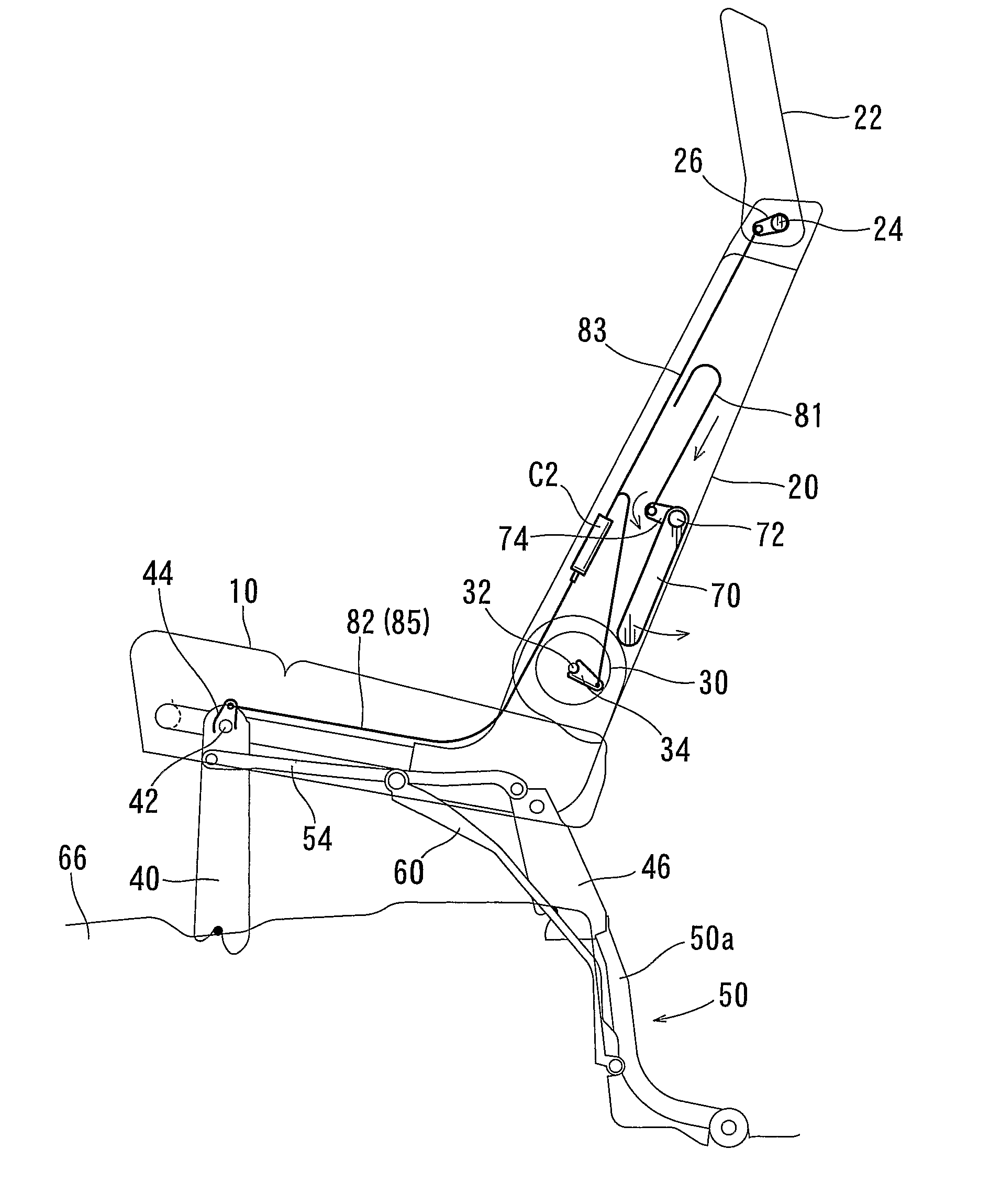
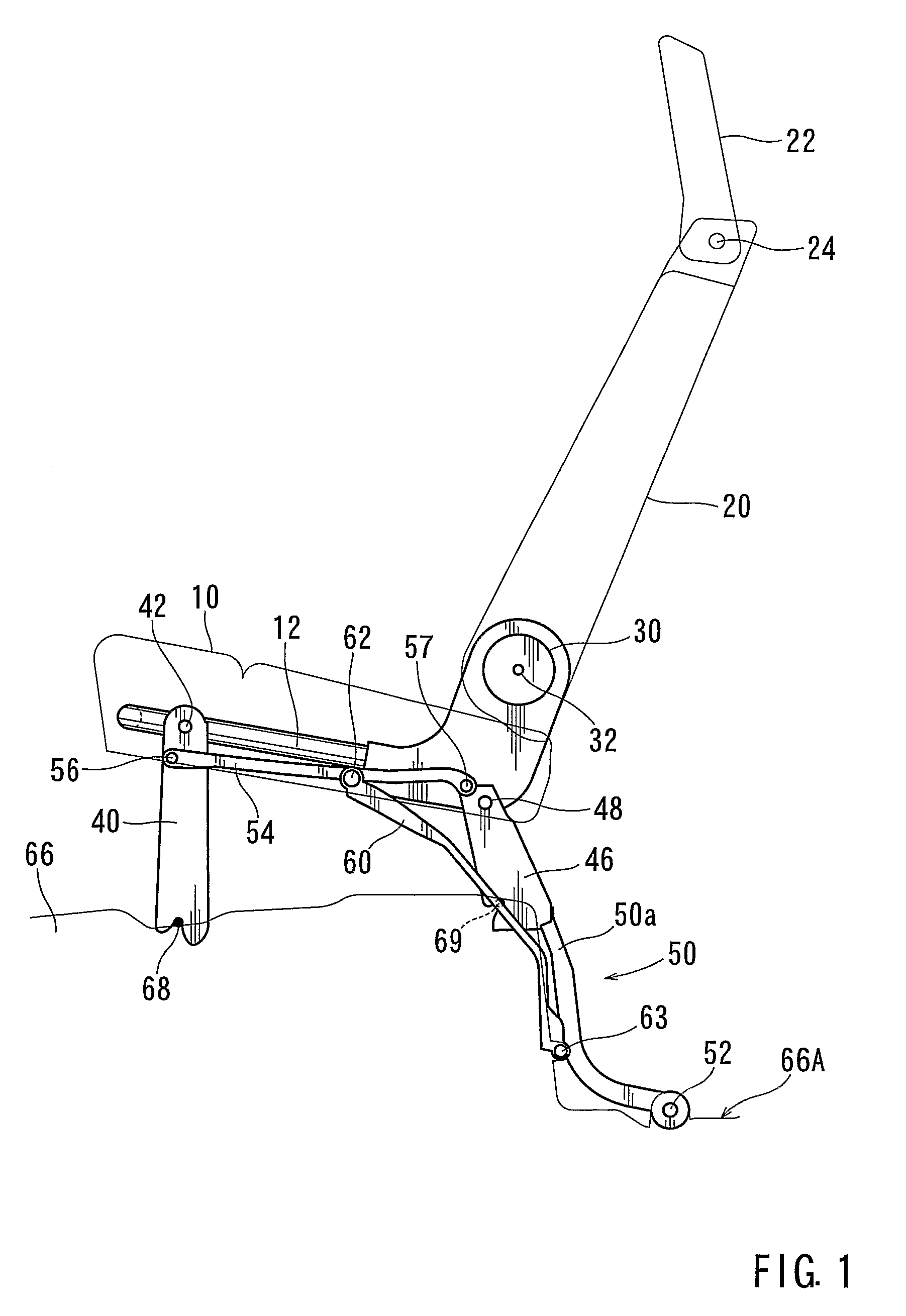
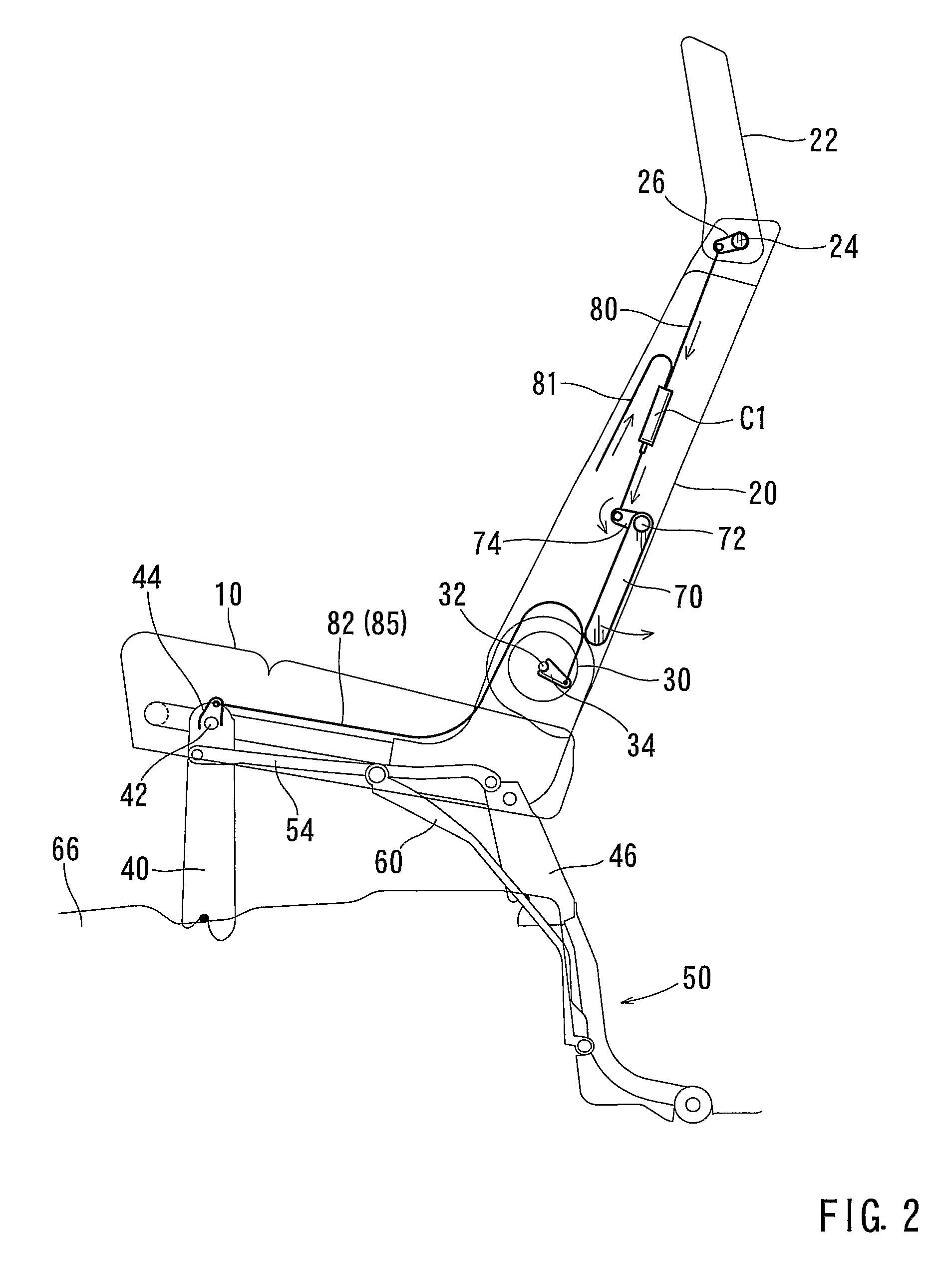
[0031]First, the present invention will be described with reference to FIGS. 1 to 8.

[0032]A vehicle seat (a retractable seat) shown in FIGS. 1 and 2 may include a seat cushion 10, a seat back 20 and a headrest 22. The seat cushion 10 is attached to a floor 66 via a pair of front legs 40 (one of which is shown for illustration purposes) and a pair of rear legs 46 (one of which is shown for illustration purposes). Further, the front legs 40 and associated members thereof may have the same structure. Therefore, a structure of one of the front legs 40 will be described hereinafter. Similarly, the rear legs 46 and associated members thereof may have the same structure. Therefore, a structure of one of the rear legs 46 will be described hereinafter.

[0033]The seat back 20 is rotatably connected to the seat cushion 10 via a pair of seat reclining mechanisms 30 (one of which is shown). Therefore, the seat back 20 can be tilted back and forth by operating the seat reclining mechanism 30 about...

second embodiment

[0050] the lever 70 can simply be operated in order to unlock the locking devices (not shown). That is, the headrest 22 can be automatically inclined forwardly when the seat is moved rearwardly. Therefore, the force required to operate the lever 70 can be further reduced.

Third Detailed Representative Embodiment

[0051]The third detailed representative embodiment will now described with reference to FIGS. 10-15.

[0052]A vehicle seat (a retractable seat) shown in FIGS. 10 and 11 may include a seat cushion 10 and a seat back 20. The seat cushion 10 is attached to a floor 66 via a pair of front legs 40 (one of which is shown for illustration purposes) and a pair of rear legs 46 (one of which is shown for illustration purposes). Further, the front legs 40 and associated members thereof may have the same structure. Therefore, a structure of one of the front legs 40 will be described hereinafter. Similarly, the rear legs 46 and associated members thereof may have the same structure. Therefore...

third embodiment

[0065]As described above, the torsion spring 100 can generate the different rotational biasing forces (the assisting force and the resisting force) depending on the rotational angles of the auxiliary link 60 relative to the cushion frame 12. That is, the torsion spring 100 may have two different biasing functions. Therefore, it is not necessary to provide an additional spring. This may lead to reduced manufacturing cost.

[0066]Naturally, various changes and modifications may be made to the present invention without departing from the scope of the invention. For example, in the third embodiment, although the torsion spring 100 is attached to the hinge pin 62, the torsion spring 100 can be attached to the support shaft 48 of the rear leg 46. In addition, the torsion spring 100 can be attached to the rotational shaft 32 of the reclining mechanism 30 such that different rotational biasing forces (an assisting force and an resisting force) depending on the rotational angles of the back f...


PUM


Abstract

A vehicle seat is taught that preferably include a seat cushion (10), a seat back (20) rotatably connected to the seat cushion via a reclining mechanism (30), front (40) and rear (46) legs removably connecting the seat cushion to a vehicle floor (66), a retracting link (50), an operating member capable of removing the front and rear legs from the floor, and a coupling link (54). The seat back can be rotated forwardly by unlocking the reclining mechanism, so as to be superimposed on the seat cushion. When the front and rear legs are removed from the floor, the seat can be moved from a use condition to a retracted condition depending on the motion of the retracting link. When the seat is moved from the use condition to the retracted condition, the coupling link rotates the front leg based on a displacement of the retracting link, thereby unlocking the reclining mechanism.

Description

TECHNICAL FIELD[0001]The present invention relates to a vehicle seat.BACKGROUND ART[0002]A conventional vehicle seat is shown in, for example, Japanese Laid-Open Patent Publication No. 2005-247104. In the seat, a seat cushion is attached to a floor via front and rear legs, so that the seat can be retained in a use condition. An upper end portion of each of the front and rear legs is rotatably connected to a cushion frame. Conversely, a lower end portion of each of the front and rear legs is removably connected to the floor. Further, each of the rear legs has a retracting link that is extended therefrom. A distal end of the retracting link is rotatably connected to a recessed portion formed in the floor via a pivot member.[0003]In order to move the seat from the use condition to a retracted condition, first, a lever (or a strap) provided on a rear surface of a seat back is pulled, so that a reclining mechanism is unlocked. Thereafter, the seat back is rotated forwardly so as to be su...

Claims


Application Information

Patent Timeline
Patent Type & Authority Patents(United States)
IPC IPC(8): B60N2/30B60N2/10
CPCB60N2/22B60N2/3011B60N2/3065B60N2/3075B60N2/309B60N2/4855B60N2/856
Inventor ITO, MAKOTOOOISHI, YOSHIHIROMURAMATSU, TOMOHIROFUJIMOTO, OSAMUDAY, ROBERT
Owner TOYOTA BOSHOKU KK
Why Eureka
Try Eureka