
Method for producing a sandwich construction, in particular a sandwich construction for the aeronautical and aerospace fields

a technology for aerospace and aeronautical fields, applied in the field of method for producing a construction, can solve the problems of comparatively time-consuming and therefore costly process, and achieve the effect of low material consumption and simplified process

Active Publication Date: 2012-03-06
AIRBUS OPERATIONS GMBH
View PDF7 Cites 12 Cited by
  • Summary
  • Abstract
  • Description
  • Claims
  • Application Information

AI Technical Summary

Benefits of technology

The present invention provides a method and construction for producing a sandwich construction for the aeronautical and aerospace fields that reduces the time required to heat the projecting portions of the construction. This is achieved by simultaneously heating the projecting portions and the core construction material using a heating material that can be applied on one side of the core construction material. The heating material is then deformed using a roller or other means to create the desired shape. The construction is formed by a foam material, prepreg material, or a dry bonded or woven fabric, and may be used for hollow or filled constructions. The method and construction provide savings in time and expense over the sequential approach.

Problems solved by technology

The approach described above has been found to have the drawback that it is necessary to initially grip each of the projecting portions of the reinforcing elements individually with the heated tongs and to then wait for a predetermined time until the projecting portion is sufficiently softened to enable it to be folded down so as to engage the core layer from behind.
This process is comparatively time-consuming and therefore costly.

Method used


Image

  • Method for producing a sandwich construction, in particular a sandwich construction for the aeronautical and aerospace fields
  • Method for producing a sandwich construction, in particular a sandwich construction for the aeronautical and aerospace fields

Examples


Embodiment Construction

[0037]The invention will be described in greater detail below on the basis of embodiments with reference to the appended drawing.

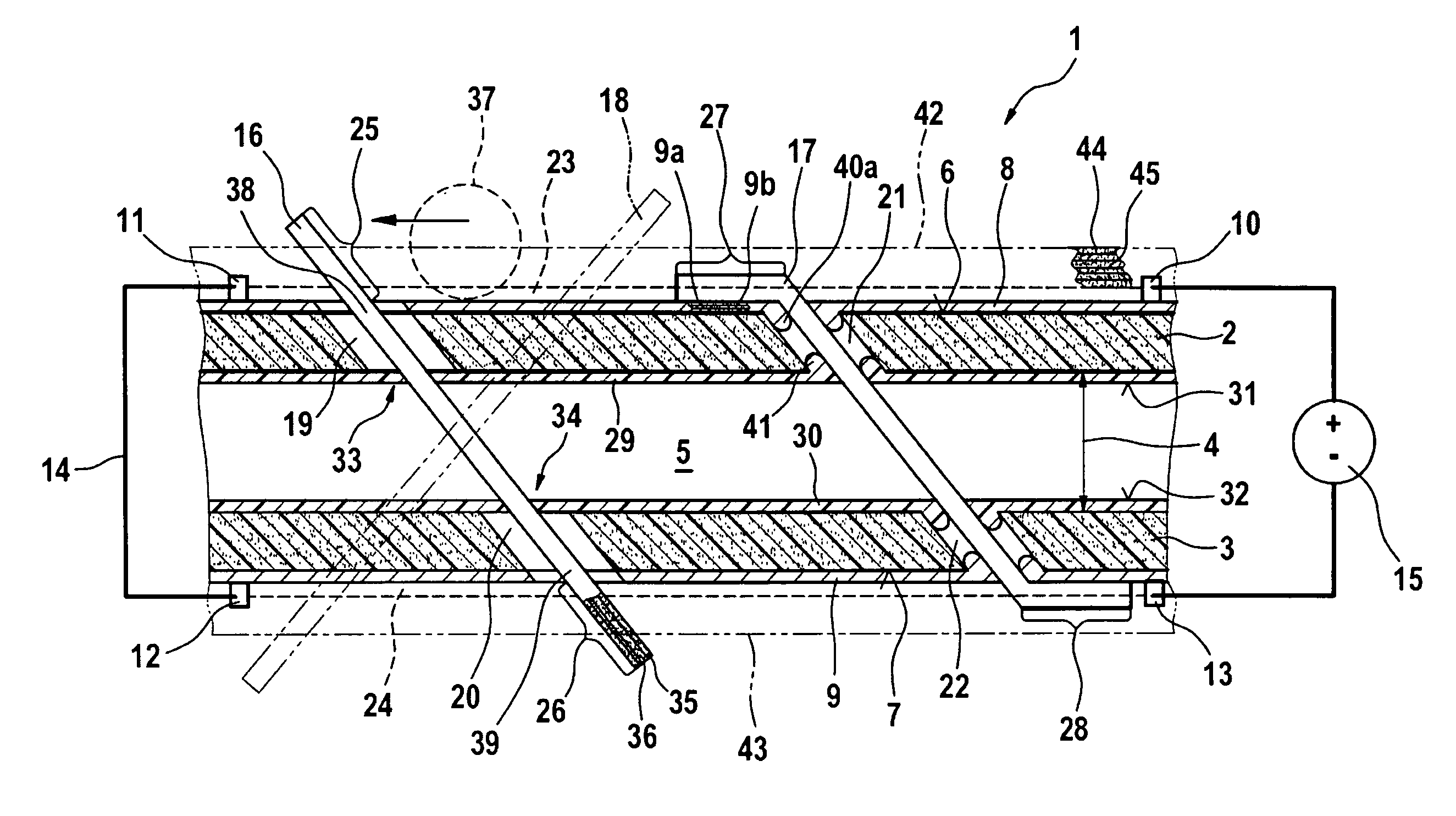
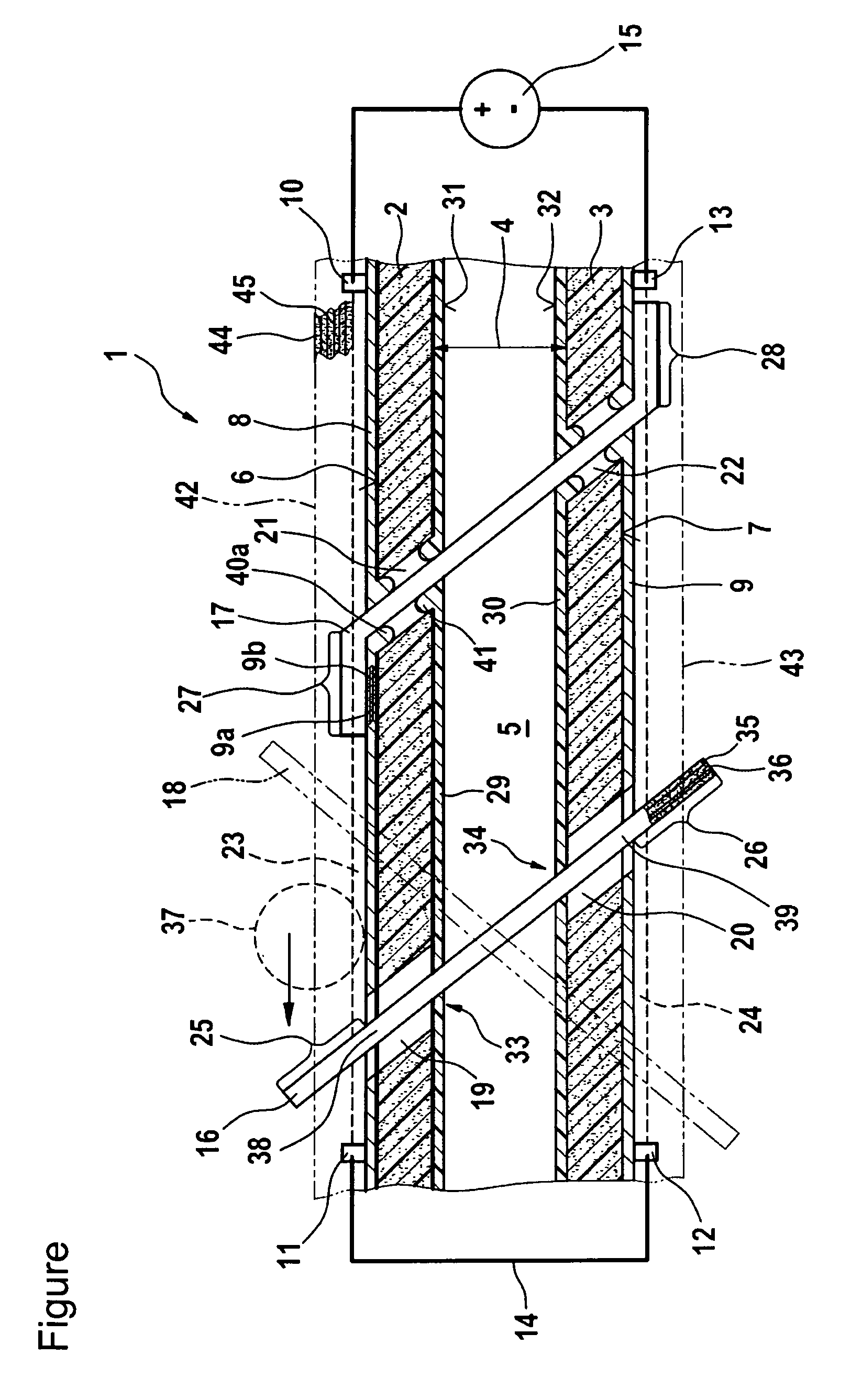
[0038]The FIGURE is a sectional view of a state in the production of a construction 1 according to a preferred embodiment of the invention.

[0039]Two core construction layers 2 and 3 are initially held at a distance 4 from one another, forming a cavity 5 between them (referred to in this document as a hollow construction). The core construction layers 2 and 3 are preferably formed from a foam, in particular a rigid foam.

[0040]In an alternative to the hollow construction, a single core construction layer may also be used (referred to in this document as a filled construction) in which the cavity denoted with the reference numeral 5 would be filled with core construction material. All of the comments below also apply to the filled construction.

[0041]The core construction layers 2, 3 are each provided on their sides 6 or 7, which are remote from one another, w...


PUM

PropertyMeasurementUnit
angleaaaaaaaaaa
currentaaaaaaaaaa
stiffnessaaaaaaaaaa

Abstract

The present invention provides a method of producing a construction, in particular a sandwich construction for the aeronautical and aerospace fields, comprising the following steps. A heating material is initially applied on one side of a core construction material. In a further step a reinforcing element is introduced into the core construction material and the heating material in such a way that the reinforcing element extends through the core construction material and the heating material and has a portion which projects beyond the heating material. The heating material is then heated to soften the projecting portion at least in regions and said projecting portion is subsequently deformed using the softened region as a pivot point to engage the core construction material from behind and to form the construction. This method is distinguished in particular by the fact that it allows the portions to be heated substantially simultaneously, and not sequentially as in the state of the art. The time saved as a result in turn has a positive effect on production costs.

Description

CROSS-REFERENCE TO RELATED APPLICATIONS[0001]This application claims the benefit under 35 U.S.C §119(e) of U.S. Provisional Application No. 61 / 024,961, filed Jan. 31, 2008, the entire disclosure of which is herein incorporated by reference.BACKGROUND OF THE INVENTION[0002]The present invention relates to a method for producing a construction, in particular a sandwich construction for the aeronautical and aerospace fields, and to a construction of this type, in particular a sandwich construction for the aeronautical and aerospace fields.[0003]In high-tech fields, such as aircraft construction, sandwich constructions have a wide range of applications due to the good stiffness and strength to density ratios thereof. A sandwich construction is generally composed of a core layer which has a cover layer on the upper and lower sides respectively thereof.[0004]In order to reinforce a sandwich construction of this type, it has become known to insert rod-shaped reinforcing elements, for examp...

Claims


Application Information

Patent Timeline
Patent Type & Authority Patents(United States)
IPC IPC(8): B32B3/06
CPCB29C65/3616B29C66/438B29C66/439B29C66/8362B29C70/24B29D24/002B29C65/3416B29C66/727B29C65/00B29C53/08Y10T29/49629B29C65/3612B29K2063/00B29K2101/10B29K2101/12B29K2105/04B29K2307/00B29K2309/08B29K2995/0005B29L2024/00Y10T29/49922B29C65/3676B29C65/3468B29C65/3492B29C65/3476B29C65/3696B29C66/12821B29C66/12861B29C66/43B29C66/45B29C66/71B29C66/7212B29C66/73753B29C66/7392B29C66/7394B29K2307/04
Inventor WEBER, HANS-JURGENENDRES, GREGOR CHRISTIAN
Owner AIRBUS OPERATIONS GMBH
Learn More