Zero clearance attachment

a technology of zero-level attachments and fixing brackets, applied in snow cleaning, way cleaning, construction, etc., can solve the problems of severe damage to buildings or other obstacles, and achieve the effect of adding more rigidity and not causing any damag

Inactive Publication Date: 2012-03-06
KOTILA WAYNE M
View PDF16 Cites 12 Cited by
  • Summary
  • Abstract
  • Description
  • Claims
  • Application Information

AI Technical Summary

Benefits of technology

[0009]The inventions many different designs, all use a strong frame forming an angle with gussets or other framing for strength, the angle can be any degree of bend to fit the desired application. The frame can be quickly attached to the end of a plow blade, bucket snow blower, or other applicable device. The inventions flex edge can be of a stiff yet forgiving material such as rubber or other applicable materials known to industry. The inventions embodiment of a flex edge can also be constructed of a forgiving but stiff material like belting, and the belting can be wrapped around a pipe or other material to add more rigidity, while still maintaining a flexible edge that will deflect away if striking a building or other obstacle and not cause any damage. The pipe or other rigid material used also provides a mounting frame for attaching a square tubing or other suitable receiver for the compression spring assembly. In this assembly the ends of the compression spring rods float unattached in over sized holes in the square tubing, and can be assembled with extension springs that run between the spring rods and the square tubing. This prevents the floating spring rods from popping out of the receiver (square tubing), if the flex edge is deflected forward, as this can happen from the forces applied if a plow blade is dragging on the ground as it is angled back.

Problems solved by technology

Prior art does not allow for close up material removal, and attempting to get close can result in severe damage to buildings or other obstacles.

Method used


Image

  • Zero clearance attachment
  • Zero clearance attachment
  • Zero clearance attachment

Examples


Embodiment Construction

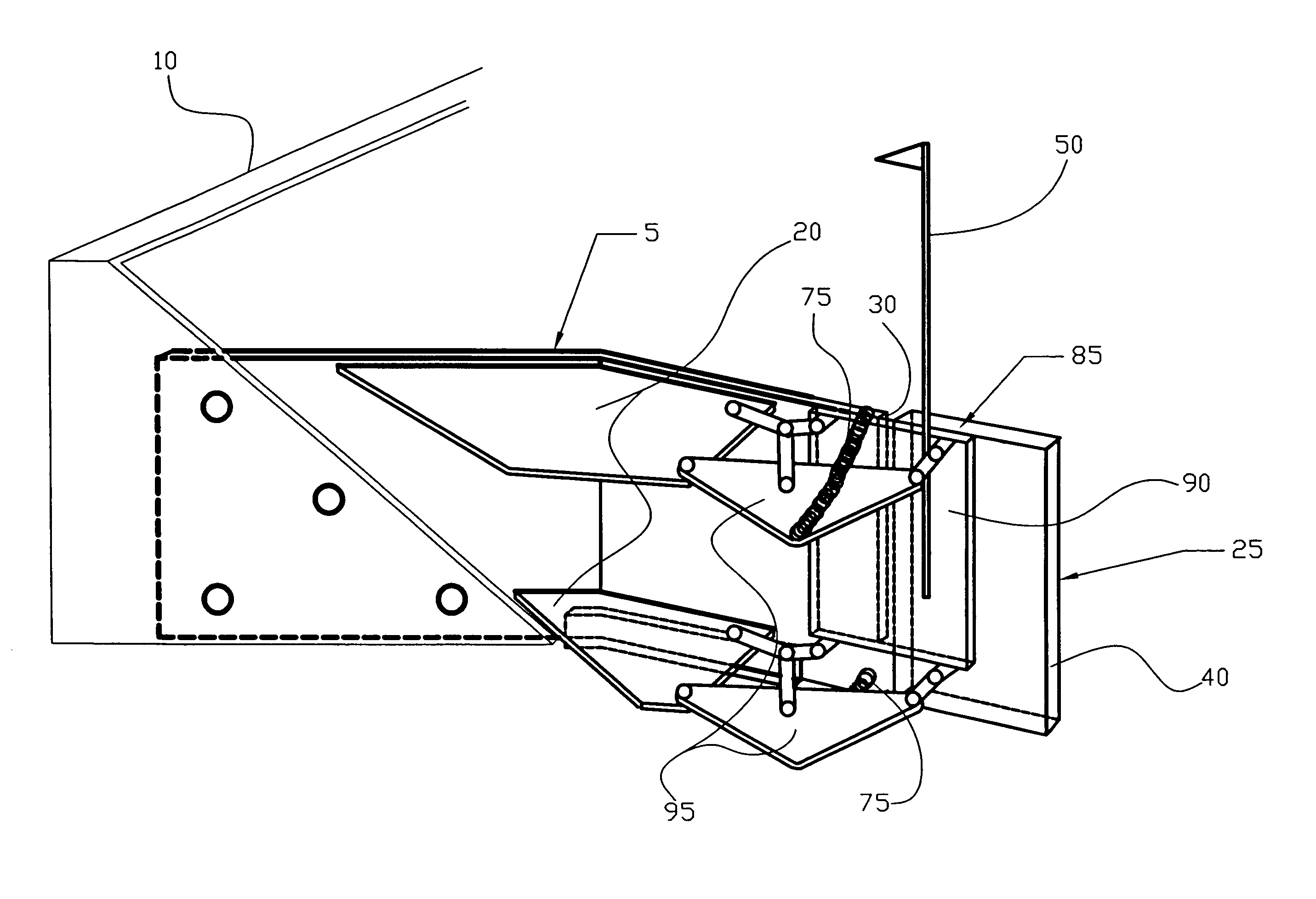
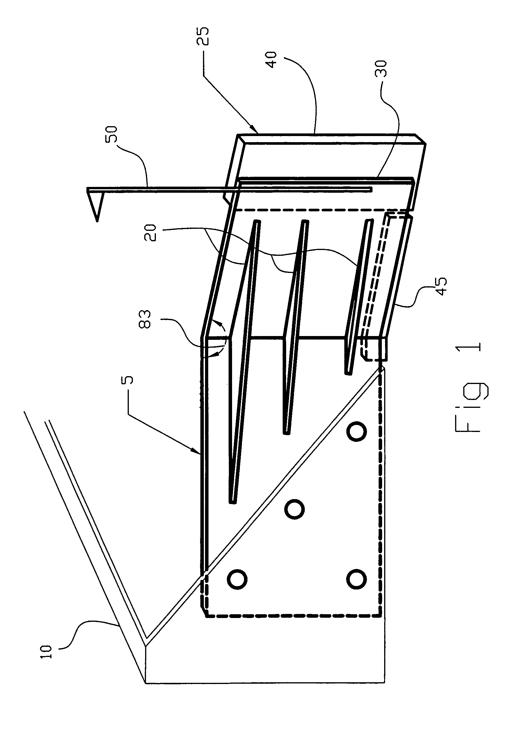
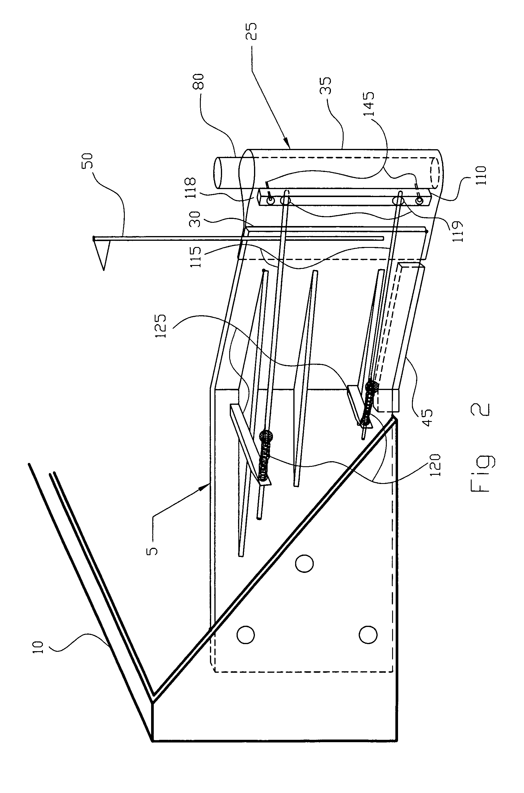
[0024]FIG. 1 in this embodiment of the present invention, The Zero Clearance Attachment (ZCA) (5) is a frame or structure and is designed for use with a conventional bucket (10). The ZCA (5) attaches to the bucket (10) with bolts, pins, welding or other preferred method. The ZCA (5) is attached to the end of the bucket (10) and angling away at an angle (83) of 45 degree, but could be of a lesser or greater degree of angle and not change the design intent. This angle (83) is supported by gussets (20) to maintain the angle (83) and add rigidity, the gussets (20) are attached (i.e. welded) to the ZCA (5). On the outward vertical end (30) of the ZCA (5) is a flexible (flex) edge (25). This flex edge is of a solid yet flexible material like rubber (40). The bottom edge of the ZCA (5) has a height adjustable and replaceable wear edge (scraper blade (45)), attached by suitable means such as bolts. The scraper blade (45) accounts for the thickness of the bucket (10), aligning the bottom of ...


PUM


Abstract

A device that allows safe and complete clearing of snow or other material away from obstacles such as, buildings, doors, vehicles, machinery, etc. The device attaches to and guides material into a plow, bucket, blower, snow blower, or other equipment allowing the machine operator to physically contact an obstacle being cleared around without causing harm or damage to the obstacle. The soft moveable flex edge of the device can touch and slide along the obstacle allowing more complete snow or other material removal. The flex edge can deflect back and away from an obstacle preventing damage to the obstacle. The device comprises a rigid frame with a flex edge on the outward end of the frame. The flex edge can embody many designs including but not limited to, a spring resistance deflection mechanism, a pivot mechanism or a retracting mechanism.

Description

CROSS REFERENCE TO RELATED APPLICATION[0001]This application claims the benefit of provisional patent application 61 / 205,943 filed 26 Jan. 2009 by the inventor Wayne M. KotilaBACKGROUND OF THE INVENTION[0002]1. Field of Invention[0003]The present invention relates to the safe and complete removal of snow, sand, or other materials away from and right up against doors, buildings, or other obstacles. The invention addresses the issue of snow or other material removal being limited to areas a safe distance away from buildings and other obstacles, resulting in snow and other materials left up against buildings, doors and other obstacles. This can result in the need to step over, climb over, or hand shovel the material away, but in many cases the material is just left where it is. This often results in stuck vehicles, loss of access, or doors frozen down, and snow left piled up can create ice dams, which can cause water to back up into buildings.[0004]The invention can be quickly attached...

Claims


Application Information

Patent Timeline
Patent Type & Authority Patents(United States)
IPC IPC(8): E01H5/04
CPCE01H5/066
Inventor KOTILA, WAYNE MICHAEL
Owner KOTILA WAYNE M
Why Eureka
Try Eureka