Adaptive advance drive control for milling machine

a technology of advance drive control and milling machine, which is applied in the direction of cutting machine, way, construction, etc., can solve the problems of construction machine lurch, construction machine lurch back, construction machine lurch forward or back, etc., and achieve the effect of reducing the reaction force and reducing the advance speed

Active Publication Date: 2012-03-06
WIRTGEN GMBH
View PDF10 Cites 41 Cited by
  • Summary
  • Abstract
  • Description
  • Claims
  • Application Information

AI Technical Summary

Benefits of technology

[0007]In one embodiment a method is provided for controlling a construction machine having a frame, a milling drum supported from the frame for milling a ground surface, a plurality of ground engaging supports engaging the ground surface and supporting the frame, and an advance drive associated with at least one of the ground engaging supports to provide motive power to the at least one ground engaging support. Motive power is applied to the advance drive and moves the construction machine forward at an advance speed. The milling drum is operated in a down cut mode. A parameter is sensed corresponding to a reaction force acting on the milling drum. A change in the parameter is detected corresponding to an increase in the reaction force. In response to detecting the change and while continuing to operate the milling drum in a down cut mode, the motive power provided to the advance drive is reduced to reduce the advance speed and thereby reduce the reaction force to prevent a lurch forward event.
[0008]In another embodiment a method is provided for controlling a construction machine having a frame and a milling drum supported from the frame for milling a ground surface. The milling drum is rotated. The rotating milling drum is lowered relative to the ground surface. A parameter corresponding to a reaction force acting on the milling drum is sensed. A change in the parameter corresponding to an increase in the reaction force is detected. In response to detecting the change and while continuing to rotate the milling drum, a rate of lowering the milling drum is slowed thereby preventing a lurch forward or lurch backward event.
[0009]In another embodiment a construction machine comprises a frame, and a milling drum supported from the frame for milling a ground surface. The milling drum is constructed to operate in a down cut mode. A plurality of ground engaging supports support the frame from the ground surface. An advance drive is associated with at least one of the ground engaging supports to provide motive power to advance the construction machine across the ground surface. A sensor is arranged to detect a parameter corresponding to a reaction force from the ground surface acting on the milling drum. An actuator is operably associated with the advance drive for controlling the motive power output by the advance drive. A controller is connected to the sensor to receive an input signal from the sensor and connected to the actuator to send a control signal to the actuator. The controller includes an operating routine which detects a change in the sensed parameter corresponding to an increase in reaction force and in response to the change reduces motive power provided to the advance drive to aid in preventing a lurch forward event of the construction machine.
[0010]In another embodiment a construction machine comprises a frame, and a milling drum supported from the frame for milling a ground surface. A plurality of ground engaging supports support the frame from the ground surface. A sensor is arranged to detect a parameter corresponding to a reaction force from the ground surface acting on the milling drum. An actuator is operably associated with the advance drive for controlling a rate at which the milling drum is lowered into the ground surface. A controller is connected to the sensor to receive an input signal from the sensor and connected to the actuator to send a control signal to the actuator. The controller includes an operating routine which detects a change in the sensed parameter corresponding to an increase in reaction force and in response to the change reduces the rate at which the milling drum is lowered to aid in preventing a lurch forward or lurch backward event of the construction machine.

Problems solved by technology

If the construction machine is operating in a down cut mode the reaction forces on the rotating milling drum may cause the construction machine to lurch forward, or if the rotating milling drum is operating in an up cut mode, the reaction forces on the milling drum may cause the construction machine to lurch back.
And if the machine is in the process of being lowered too fast into the cut the reaction force on the rotating milling drum may cause the construction machine to lurch forward or backward depending on the cutting mode, i.e. at down-cut mode or up-cut mode.

Method used


Image

  • Adaptive advance drive control for milling machine
  • Adaptive advance drive control for milling machine
  • Adaptive advance drive control for milling machine

Examples


Embodiment Construction

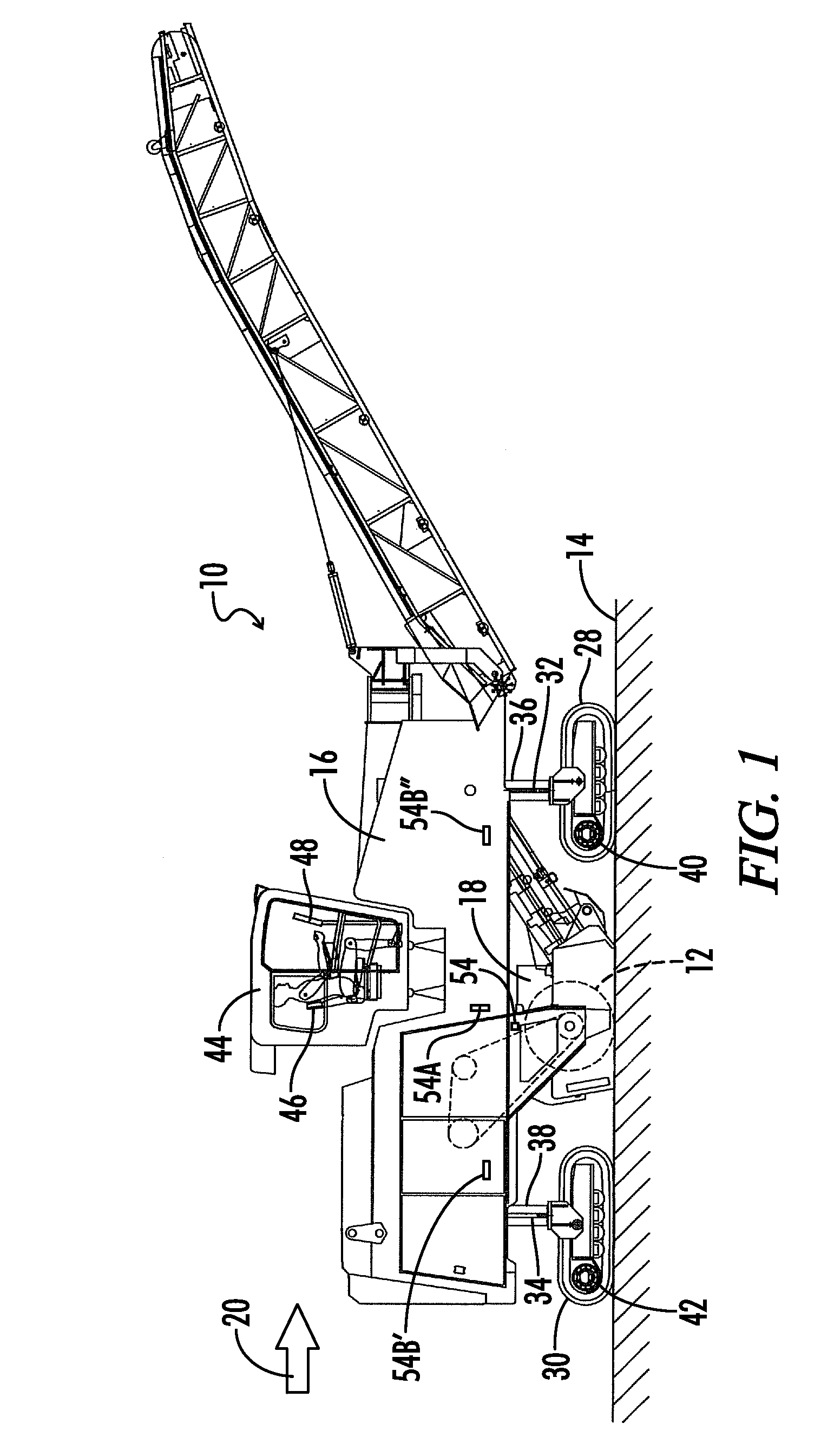
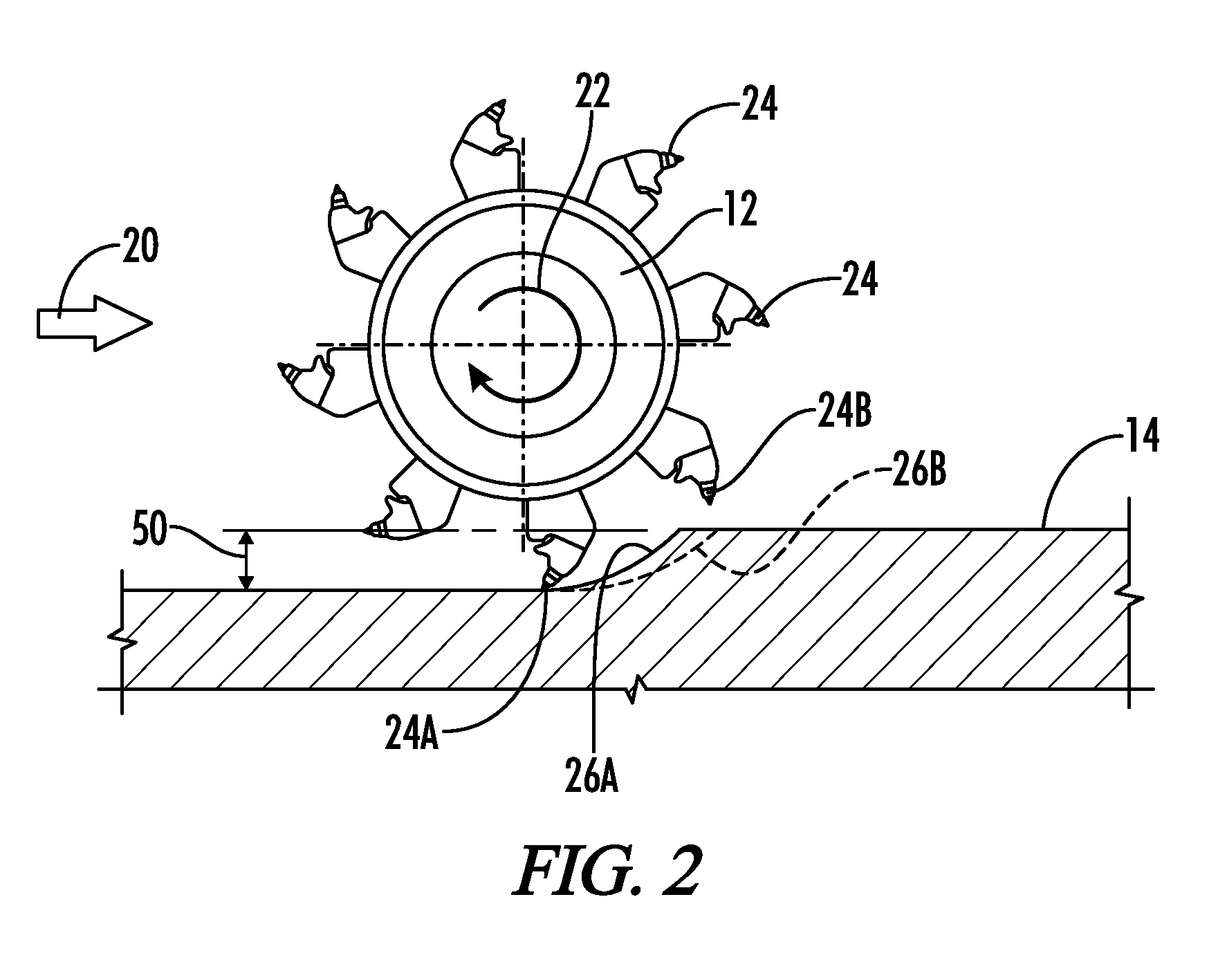
[0021]FIG. 1 shows a side elevation view of a construction machine generally designated by the numeral 10. The construction machine 10 illustrated in FIG. 1 is a milling machine. The construction machine 10 may also be a stabilizer / recycler or other construction machine of the type including a milling drum 12. The milling drum 12 is schematically illustrated in FIG. 2 in engagement with a ground surface 14.

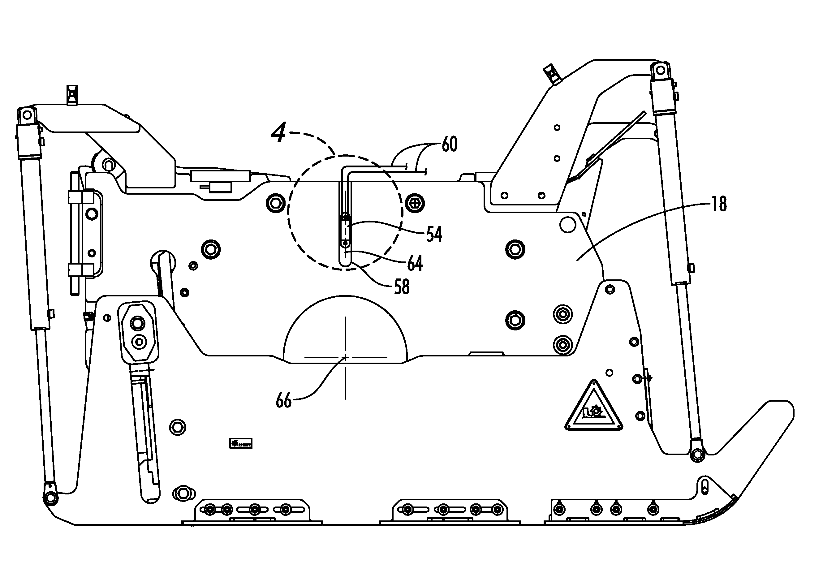
[0022]The construction machine 10 of FIG. 1 includes a frame 16 and a milling drum housing 18 attached to the frame 16. The milling drum 12 is rotatably supported within the milling drum housing 18.

[0023]The milling drum 12 of FIG. 2 is shown schematically operating in a down cut mode. In the down cut mode, the construction machine 10 is moving forward from left to right in the direction indicated by the arrow 20 of FIGS. 1 and 2. The milling drum 12 is rotating clockwise as indicated by arrow 22. The milling drum 12 has a plurality of cutting tools 24 mounted thereon. Each of the...


PUM


Abstract

An adaptive advance control system for a construction machine senses the reaction forces applied by the ground surface to a milling drum, and in response to the sensed changes in those reaction forces controls the motive power applied to an advance drive of the machine. Early and rapid detection of such changes in reaction forces allow the control system to aid in preventing lurch forward events of the construction machine.

Description

BACKGROUND OF THE INVENTION[0001]1. Field of the Invention[0002]The present invention relates generally to drive control systems for construction machines of the type including a milling drum, such as for example milling machines, surface miners or stabilizer / recycler machines. An adaptive advance drive control system for such machines aids in the prevention of lurch forward events when the machine is operating in a down cut mode.[0003]2. Description of the Prior Art[0004]During the normal operation of a construction machine having a milling drum, it is desirable that the operator be able to maintain control over the forward or rearward motion of the machine, regardless of the operation of the milling drum. If the reaction forces exerted by the ground surface on the milling drum exceed the control forces applied to the milling drum by the weight, motive force and braking force of the construction machine, then a lurch forward or lurch backward event of the construction machine may o...

Claims


Application Information

Patent Timeline
Patent Type & Authority Patents(United States)
IPC IPC(8): E21C35/08
CPCE01C23/088
Inventor MENZENBACH, CHRISTOPHMAHLBERG, AXELLANGE, HERBERTBARIMANI, CYRUSHAHN, GUNTER
Owner WIRTGEN GMBH
Why Eureka
Try Eureka