
Head chip, liquid jet head, liquid jet recording device, and method of manufacturing the head chip

a manufacturing method and liquid jet technology, applied in the direction of printing, inking apparatus, etc., can solve the problems of short circuit between the terminals of the actuator plate b>15, the wiring of the flexible substrate, and the risk of so as to improve the electric reliability and reduce the number of terminals. , the effect of preventing the short circuit between the terminals

Inactive Publication Date: 2012-03-06
SII PRINTEK
View PDF11 Cites 2 Cited by
  • Summary
  • Abstract
  • Description
  • Claims
  • Application Information

AI Technical Summary

Benefits of technology

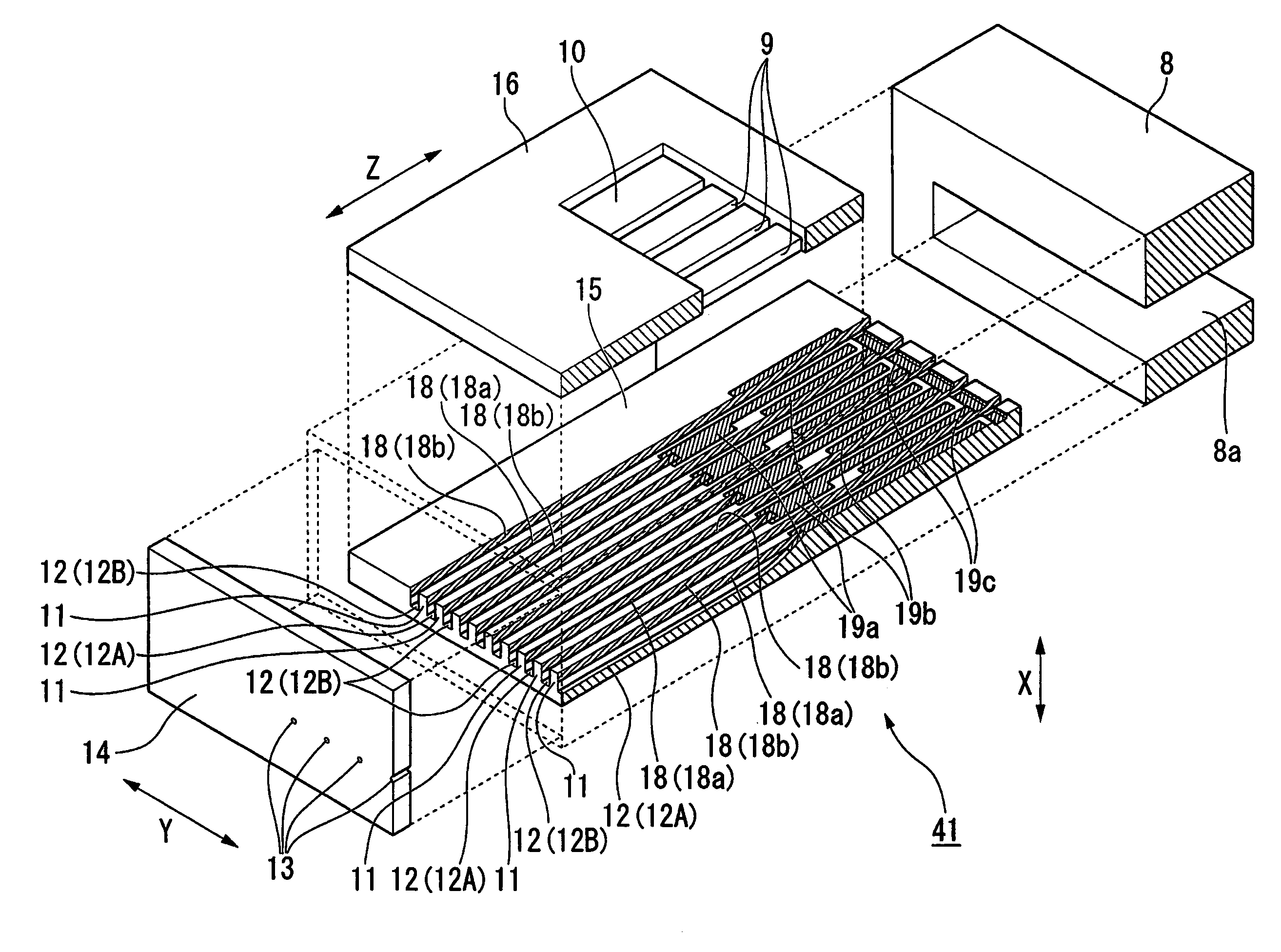
The present invention provides a head chip, liquid jet head, liquid jet recording device, and method of manufacturing the head chip that can prevent short-circuit between terminals, facilitate alignment when mounting a flexible substrate, and improve the operation accuracy of the piezoelectric element. The head chip includes an actuator plate with common electrodes and nozzles, a pair of piezoelectric elements that hold the nozzles in between, common terminals, and an integrated plate with common terminals and drive terminals. The integrated plate has integrated terminals connected to the common terminals and drive terminals, and an integrated wiring that connects the integrated terminals to the common terminals. The integrated terminals and drive terminals are arranged at the ends of the actuator plate, reducing the number of terminals and allowing for wider pitches between them. The integrated wiring includes through-holes with contact plugs to securely connect the integrated terminals and common terminals. The liquid jet recording device includes the liquid jet head and liquid supply means, and the method of manufacturing the head chip includes aligning the through-holes and removing adhesive from the through-holes.

Problems solved by technology

For that reason, there is a risk that those terminals may be short-circuited when the flexible substrate 90 is mounted.
As a result, it is difficult to align the respective terminals of the actuator plate 15 with the wirings of the flexible substrate 90.
However, the technology of JP 09-29977 A has such a problem that the intervals of the electrode extraction parts are widened, and hence the piezoelectric ceramics substrate large in width is required, resulting in the upsized ink jet head.

Method used


Image

  • Head chip, liquid jet head, liquid jet recording device, and method of manufacturing the head chip
  • Head chip, liquid jet head, liquid jet recording device, and method of manufacturing the head chip
  • Head chip, liquid jet head, liquid jet recording device, and method of manufacturing the head chip

Examples


modified example

[0082]FIG. 8 is a plan view of a head chip according to a modified example of the embodiment. In this modified example, an integrated plate 80 different from the cover plate 16 is provided, and the integrated wiring 70 and the contact plugs 75 are formed on the integrated plate 80. The integrated plate 80 is made of the same ceramic-based material as that of the actuator plate 15, and has the same linear thermal expansion coefficient as that of the actuator plate 15. Accordingly, as in the above-mentioned embodiment, the through-holes 74 of the integrated plate 80 can be readily aligned to the common terminals 19a and the integrated terminals 19d formed on the actuator plate 15.

[0083]In this modified example, however, there is a need to provide the integrated plate 80 for forming the integrated wiring 70 in addition to the cover plate 16. On the contrary, in the above-mentioned embodiment, the integrated wiring is formed on the cover plate itself, whereby the manufacturing costs can...


PUM


Abstract

A head chip for a liquid jet recording device has a pair of piezoelectric elements that form a liquid jet channel therebetween, a common electrode formed on a surface of each piezoelectric element on the liquid jet channel side, and a drive electrode formed on an opposite surface of the piezoelectric element. A cover plate is joined so as to cover a common terminal connected to the common electrode, and an integrated wiring that integrates and electrically connects all of the common terminals is formed on a surface of the cover plate. The integrated wiring is connected to the common terminals through the contact plugs formed in through-holes of the cover plate. Integrated terminals connected to the integrated wiring and drive terminals connected to the drive electrodes are arranged in line at an end of an actuator plate.

Description

BACKGROUND OF THE INVENTION[0001]1. Field of the Invention[0002]The present invention relates to a head chip, a liquid jet head, a liquid jet recording device, and a method of manufacturing the head chip.[0003]2. Description of the Related Art[0004]In recent years, there have been provided a large number of liquid jet type recording devices that eject an ink droplet on a recording medium such as a recording paper for recording an image or a character thereon. For example, a printer or a facsimile is an example thereof. The recording device supplies ink to a head chip from an ink tank through an ink supply pipe, and ejects ink onto the recording medium from a nozzle of the head chip for recording.[0005]FIG. 9 is a plan view of a head chip according to a related art, and FIG. 10 is a cross-sectional view taken along the line E-E of FIG. 9. As illustrated in FIG. 10, a head chip 41 includes an actuator plate 15 with a plurality of channels 12, a nozzle plate 14 with nozzles 13 that com...

Claims


Application Information

Patent Timeline
Patent Type & Authority Patents(United States)
IPC IPC(8): B41J2/045
CPCB41J2/14209B41J2/1609B41J2/1623B41J2002/14491B41J2202/18
Inventor KOSEKI, OSAMU
Owner SII PRINTEK
Learn More