Load testing apparatus and cap for load testing apparatus

Active Publication Date: 2017-11-09
TATSUMI
View PDF1 Cites 0 Cited by
  • Summary
  • Abstract
  • Description
  • Claims
  • Application Information

AI Technical Summary

Benefits of technology

[0027]According to one or more embodiments of the present invention, a load testing apparatus or the like i

Problems solved by technology

The conductive material is unlikely to cause damages such as cracks compared with th

Method used


Image

  • Load testing apparatus and cap for load testing apparatus
  • Load testing apparatus and cap for load testing apparatus
  • Load testing apparatus and cap for load testing apparatus

Examples


Embodiment Construction

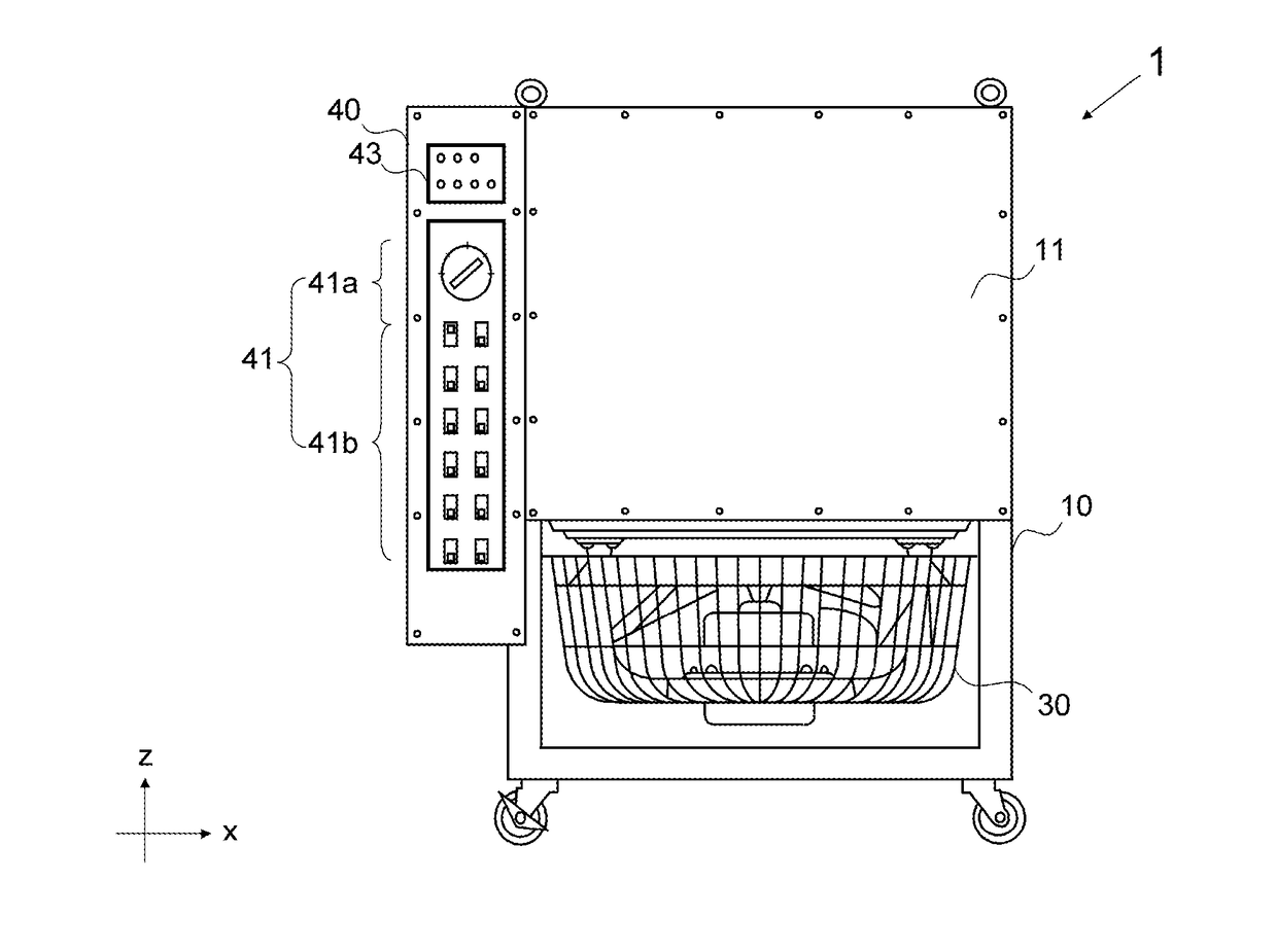
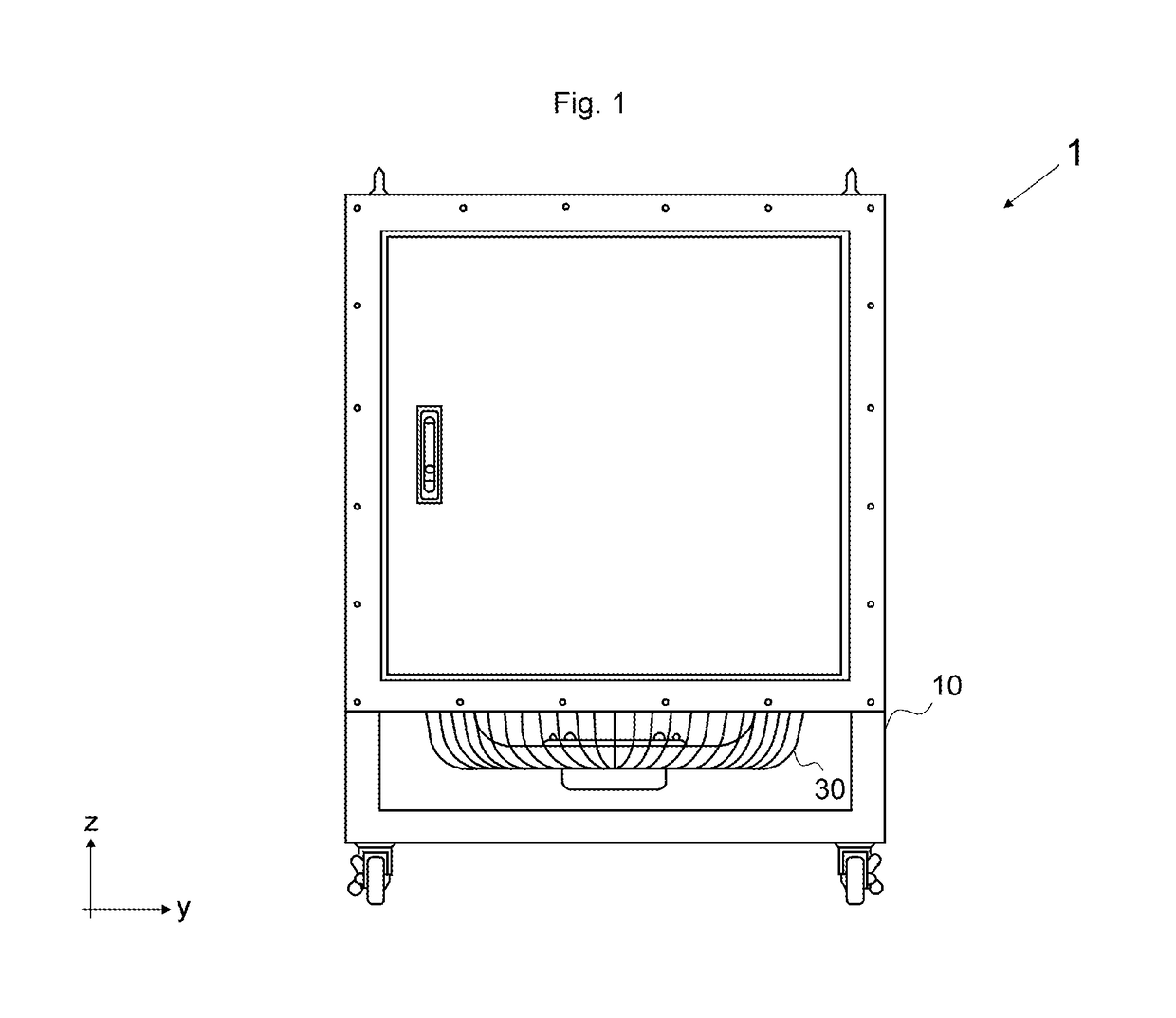
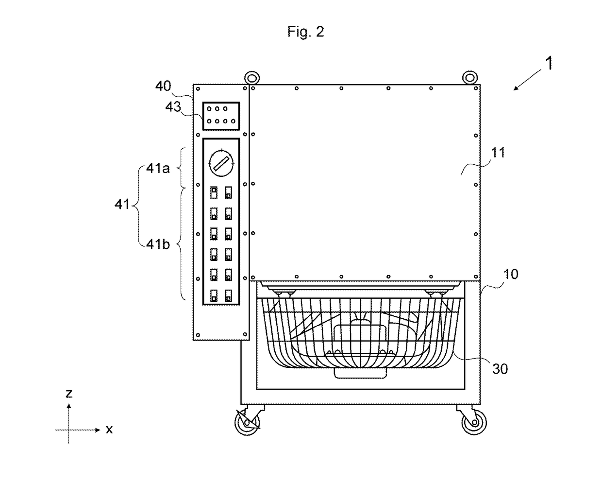
[0044]Hereinafter, the present embodiment will be described with reference to the drawings. A dry load testing apparatus 1 according to the present embodiment includes a frame 10, a resistance unit 20, a cooling unit 30, and a connection switching unit 40 (FIGS. 1 to 12).

[0045]Note that a horizontal direction in which the connection switching unit 40 and the frame 10 are arranged is defined as an x-direction, a horizontal direction perpendicular to the x-direction is defined as a y-direction, and a vertical direction perpendicular to the x-direction and the y-direction is defined as a z-direction for description of the directions.

[0046]Additionally, the cross-sectional structure views in FIGS. 7, 12, 13, and 16 illustrate not a cross-section but a state in a side surface view as for a resistance wire 61 and heat radiation fin 69 to easily understand the structures.

[0047]The frame 10 houses the resistance unit 20 in an upper stage and the cooling unit 30 in a lower stage. Additionall...


PUM


Abstract

A load testing apparatus includes: a resistance unit including a plurality of resistors adapted to receive power supply from a test target power source and a wall adapted to hold both ends of each of the plurality of resistors; and a cover attached to a frame holding the resistance unit and adapted to protect the wall and a portion included in a terminal of the resistor and projecting and exposed from the wall. Each of the resistors includes a cap. The cap has an insulation property and is attached to the portion included in the terminal and projecting from the wall. The cover is made of a conductive material. The cap is arranged between the cover and the portion included in the terminal and projecting from the wall.

Description

CROSS-REFERENCE TO RELATED APPLICATIONS[0001]This application is a continuation application of International Patent Application No. PCT / JP2016 / 055155 filed on Feb. 23, 2016, which claims priority to Japanese Patent Application No. JP2015 / 096151 filed on May 11, 2015, the entire contents of which are incorporated by reference.TECHNICAL FIELD[0002]The present invention relates to a load testing apparatus.BACKGROUND ART[0003]In the related art, there is a proposed dry load testing apparatus to perform a load test for a power generator as disclosed in Patent Literature 1.CITATION LISTPatent Literature[0004]Patent Literature 1: JP 2010-25752 A[0005]In a dry load testing apparatus, a plurality of resistors is held in a frame body, but a part of the resistor such as a terminal may project from the frame body.[0006]A cover is needed to protect the portion projecting from the frame body, but there may be probability that short circuit may occur when the cover contacts the terminal.SUMMARY OF...

Claims


Application Information

Patent Timeline
IPC IPC(8): G01R31/34G01R31/28
CPCG01R31/2879G01R31/34G01R31/40G01R1/203G01R1/206
Inventor KONDO, TOYOSHI
Owner TATSUMI
Why Eureka
Try Eureka