
Method of manufacturing high power array type semiconductor laser device

a laser device and array technology, applied in semiconductor lasers, semiconductor devices for light sources, light and heating apparatus, etc., can solve the problems of affecting the efficiency of the manufacturing process and yield, the inability to manufacture a single semiconductor laser device with more than tens of watts, and the heat in the laser array itself, so as to achieve efficient improvement of the metal bonding process of the semiconductor laser array and prevent short circuit

Inactive Publication Date: 2012-04-10
SAMSUNG ELECTRONICS CO LTD
View PDF19 Cites 2 Cited by
  • Summary
  • Abstract
  • Description
  • Claims
  • Application Information

AI Technical Summary

Benefits of technology

The present invention provides a method for manufacturing an array type semiconductor laser device that efficiently improves the metal bonding process of a semiconductor laser array to a base, thereby preventing short circuit due to metal bonding material melted during the bonding process. The method includes steps of forming electrodes on the semiconductor laser arrays, depositing a metal bonding layer on the second electrode, dicing the wafer, mounting the semiconductor laser arrays on a base, and melting the metal bonding layer to fix the semiconductor laser array on the base. The method also includes steps of forming a photoresist pattern, depositing the metal bonding layer in the photoresist pattern, and removing the photoresist pattern to form the metal bonding layer. The metal bonding layer can be made of various metals and the base can be a ceramic substrate or a metal substrate with excellent heat conductivity.

Problems solved by technology

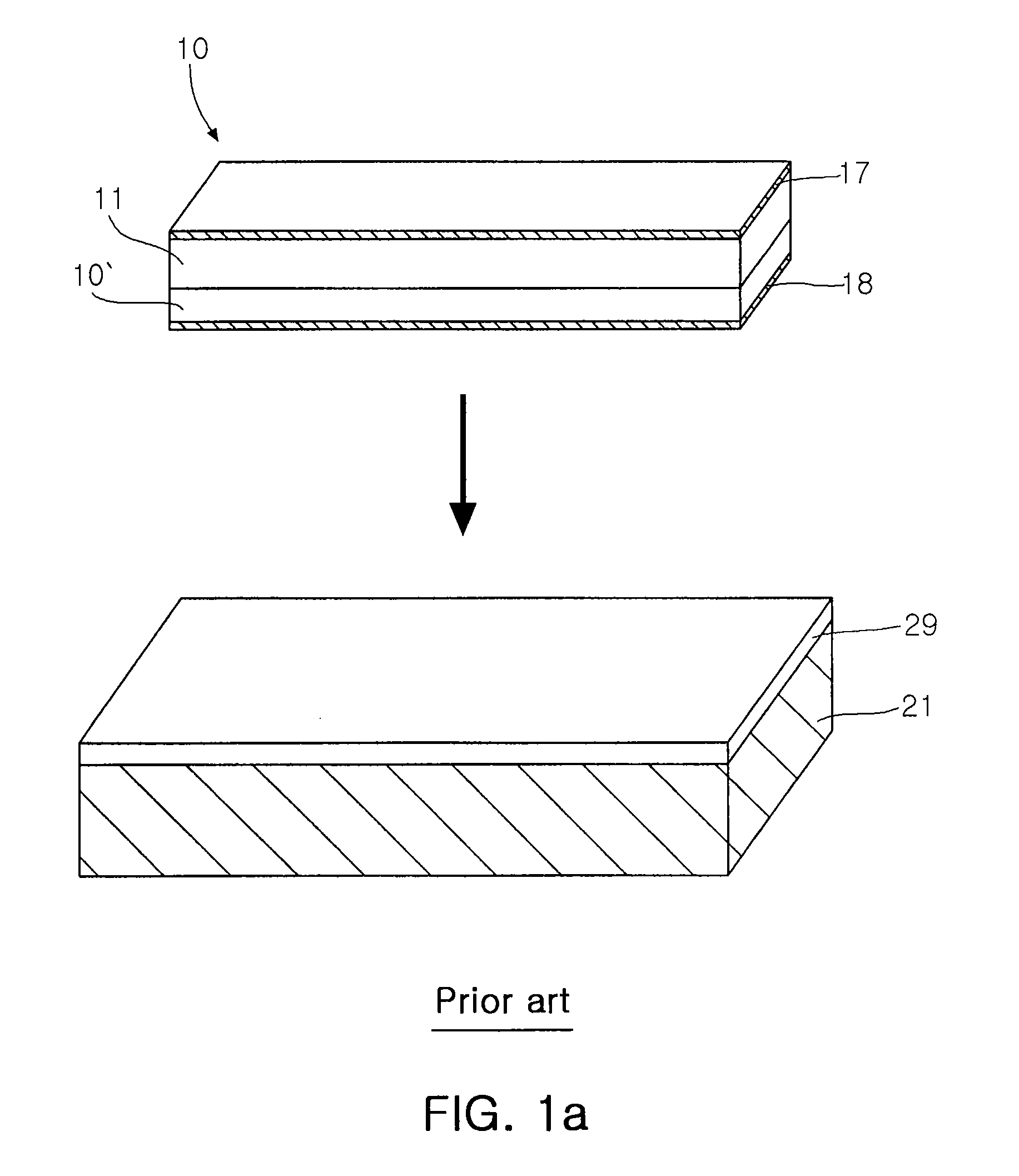
In general, it is impossible to manufacture a laser apparatus of more than tens of watts with a single semiconductor laser device.
In order to obtain light output of tens of watts, high current exceeding tens of amperes is applied, causing a considerable amount of heat in the laser array itself.
However, the base is usually manufactured for each unit package, and thus requires an individual deposition process of the metal bonding layer, which adversely affects the efficiency of the manufacturing process and a yield.
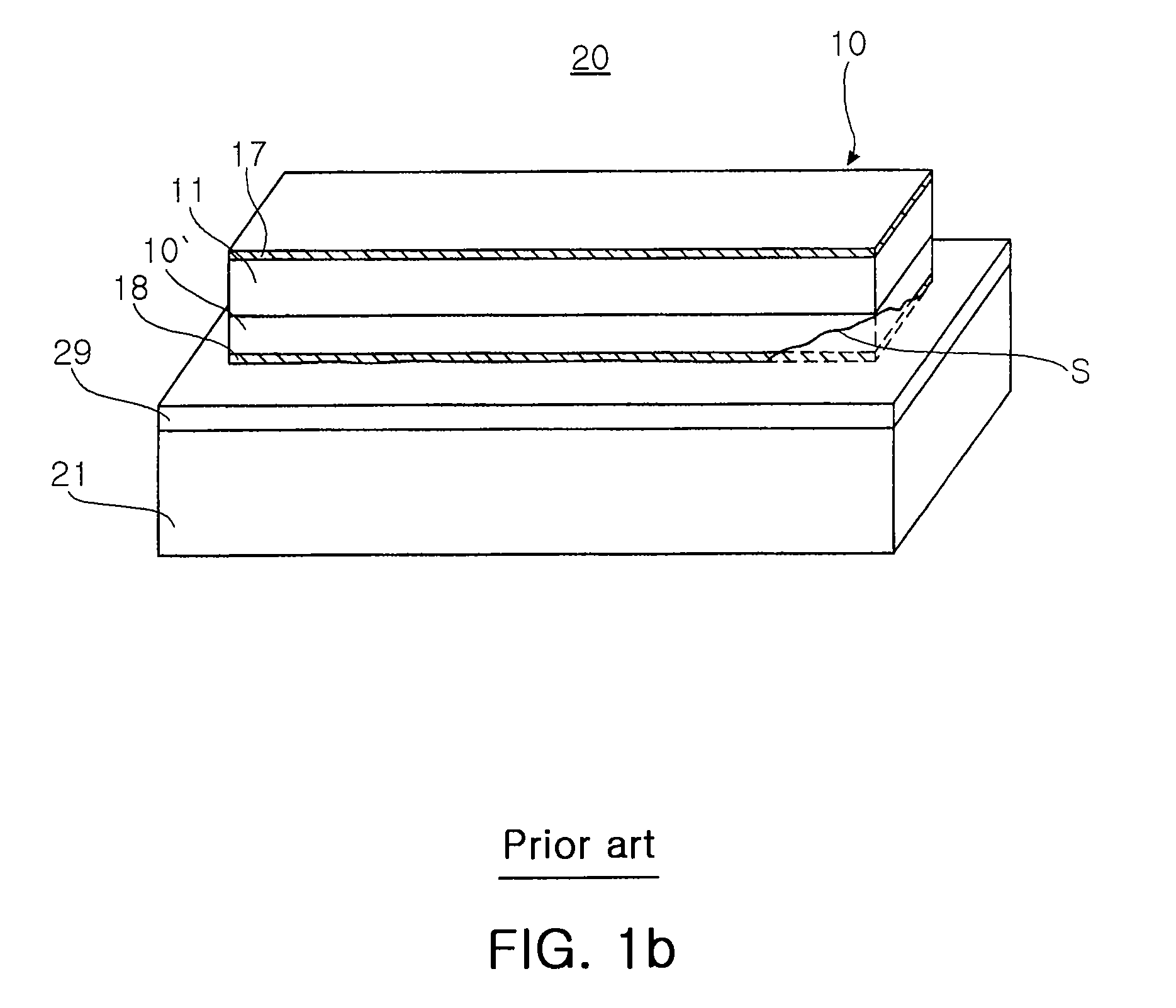
Further, as shown in FIG. 1b, when the laser array is heat-pressed on an upper surface of the base with the metal bonding layer provided thereon, the metal bonding material being melted for bonding may spread along the surface of the semiconductor laser array as denoted by the reference sign S, potentially causing short circuit of the laser.

Method used


Image

  • Method of manufacturing high power array type semiconductor laser device
  • Method of manufacturing high power array type semiconductor laser device
  • Method of manufacturing high power array type semiconductor laser device

Examples


Embodiment Construction

[0032]Exemplary embodiments of the present invention will now be described in detail with reference to the accompanying drawings.

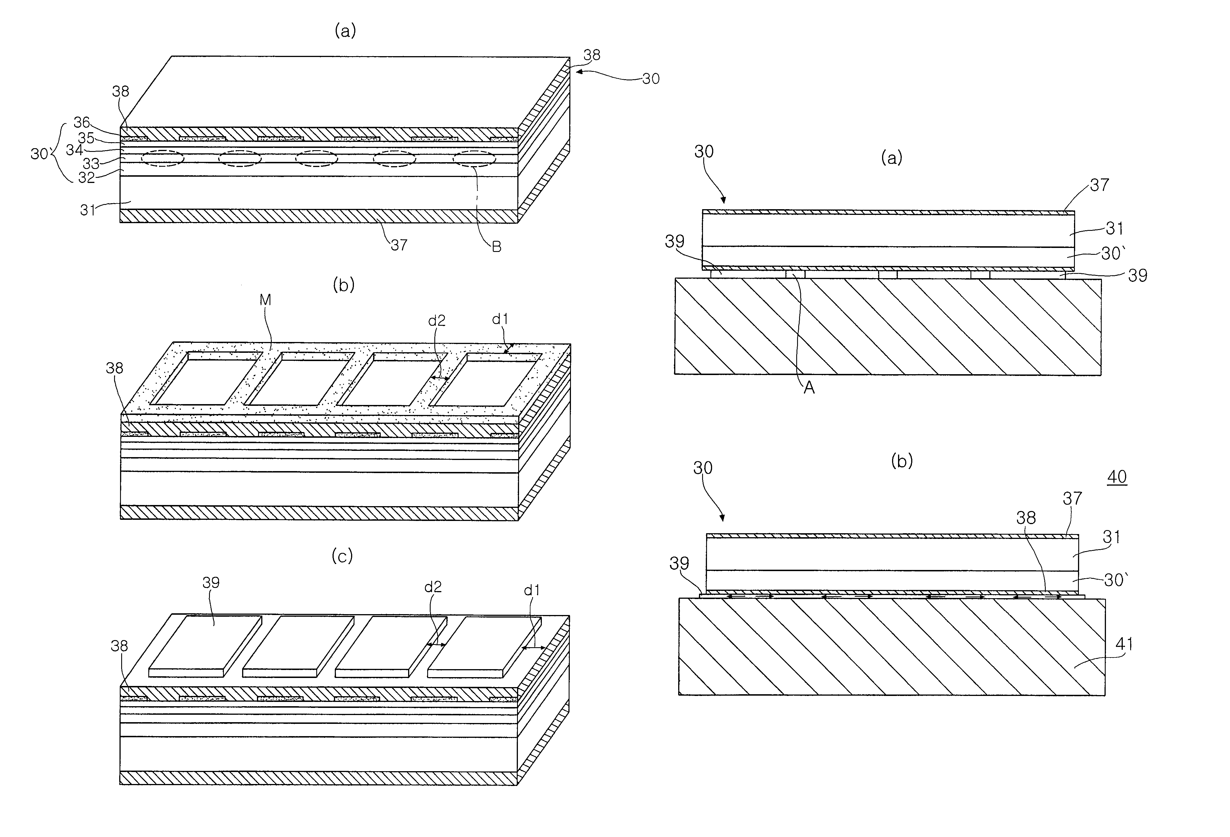
[0033]FIG. 2(a) to 2(c) are perspective views illustrating the procedures of fabricating a semiconductor laser array in a method of manufacturing an array type semiconductor laser device according to an embodiment of the present invention.

[0034]For the sake of convenience, the drawing exemplifies only one semiconductor laser array, but in actuality, the method is conducted at wafer level, and the semiconductor laser array should be understood as a wafer composed of a plurality of semiconductor laser arrays similar to the one shown in the drawing.

[0035]First, as shown in FIG. 2a, the semiconductor laser array 30 is fabricated. The method of fabricating the semiconductor laser array 30 can entail forming a first conductivity clad layer 32, an active layer 33, a second conductivity clad layer 34 and a second conductivity contact layer 35 on a first conductivi...


PUM


Abstract

A method of manufacturing an array type semiconductor laser device. The method includes forming first and second electrodes on lower and upper surfaces of a wafer comprising a plurality of semiconductor laser arrays having a plurality of laser emission regions, and forming a metal bonding layer on the second electrode of the wafer. The method also includes dicing the wafer into the semiconductor laser arrays and mounting each of the individually separated semiconductor laser arrays on a base with the surface of the metal bonding layer in contact with the base. The method further includes melting the metal bonding layer to fix the mounted semiconductor laser array on the base.

Description

CLAIM OF PRIORITY[0001]This application claims the benefit of Korean Patent Application No. 2006-0017420 filed on Feb. 22, 2005, in the Korean Intellectual Property Office, the disclosure of which is incorporated herein by reference.BACKGROUND OF THE INVENTION[0002]1. Field of the Invention[0003]The present invention relates to a high power semiconductor laser device and, more particularly, to a method of manufacturing a semiconductor laser device which includes an efficiently improved metal bonding process of a high power semiconductor laser array.[0004]2. Description of the Related Art[0005]Recently, high power semiconductor laser devices are extensively used in various applications such as industrial and medical fields including optical communication, optical recording devices, welding and dicing, and are also beginning to be applied to visible ray lasers for display, and thus expected to have further expanded applications.[0006]In general, it is impossible to manufacture a laser...

Claims


Application Information

Patent Timeline
Patent Type & Authority Patents(United States)
IPC IPC(8): H01L21/30
CPCH01S5/0206H01S5/0425H01S5/0201H01S5/0224H01S5/02272H01S5/4031H01S5/04256H01S5/026H01S5/0234H01S5/0237F21S2/005F21V19/0055F21V17/12F21V14/02F21Y2115/10
Inventor MA, BYUNG JIN
Owner SAMSUNG ELECTRONICS CO LTD
Learn More